|
|
Idle Air Control | |
|
|
Up
|
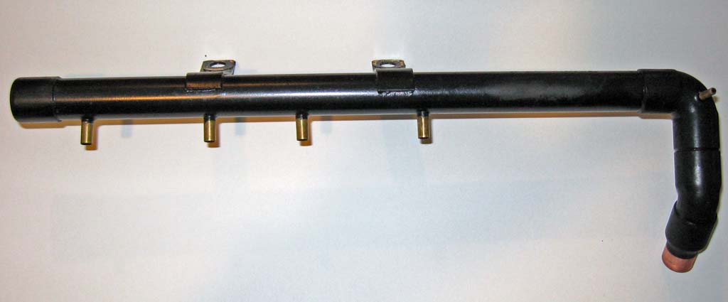
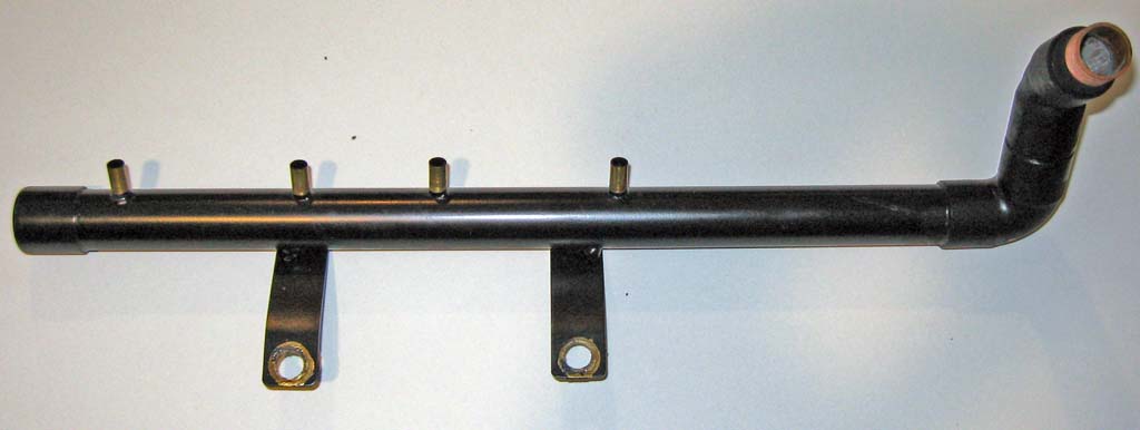
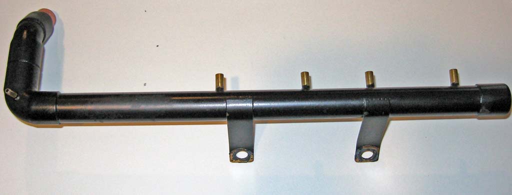
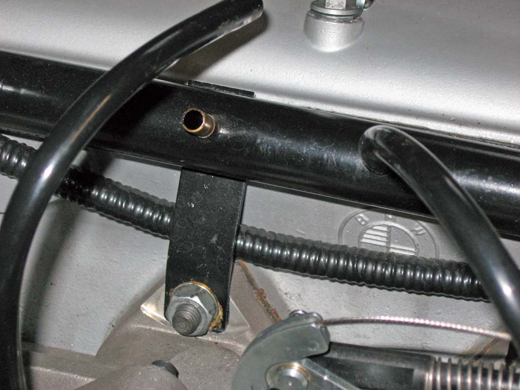
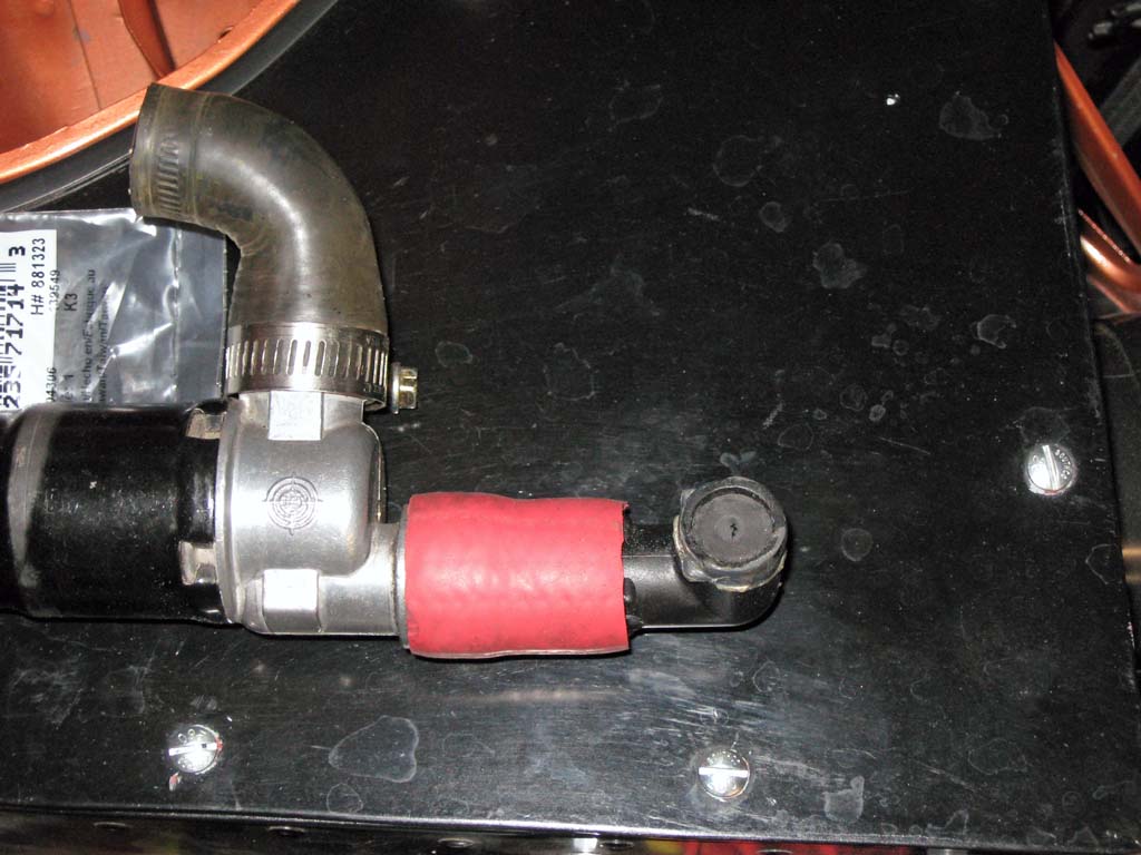
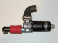
Some close-ups of the vacuum distribution pipe. The idle valve connects to the large open end. The four ports along the long pipe go to the throttle bodies, after the throttle valve. The small port on the elbow is for the MAP sensor. The pipe was made out of copper and brass tubing soldered together with brass mounting straps also soldered on.
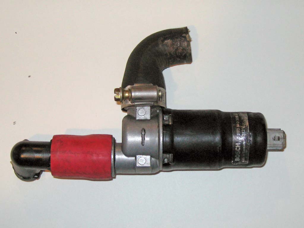
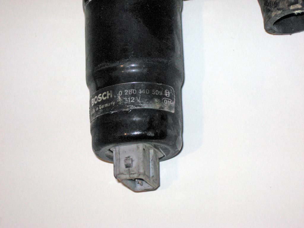
This is the idle valve I used. It is a Bosch part# 0 280 140 509. This is a 3-wire PWM style valve used on many late 80's to early 90's cars. They show up all the time on ebay.
The way this type of valve works is that the center pin is connected to +12V. When you ground one side pin the valve opens, when you ground the other side the valve closes. By pulsing the ground connections you can vary the valve's position.
This resistor circuit is what I am currently using. It works well but there is a little bit of variability in the absolute valve position for a given PWM. A more sophisticated way to control the three wire valve is with a circuit that will toggle the two ground connections on opposite directions based on the input from one PWM signal. Glenn's Garage offers such a driver circuit. I plan on upgrading to this circuit in the near future. Balancing The Idle Air Circuit After driving with the above setup for about a year, I decided to try to fix some of the tuning issues I was still having with my mixture when the idle valve was open for fast idle. The problem I was experiencing was that the fast idle mixture was always going too rich or too lean. I could not get a stable fast idle mixture across the fast idle RPM range and the coolant temperature range. I could play with the warm up and VE table values and get a narrow range of RPMs and temperatures to work but not the entire operating range. One of these problems was a miss-match in the air flow between the inlet to the idle air valve which is about 16mm in diameter and the individual hoses supplying the ITBs with air which are about 6mm in diameter. What was happening was when the idle air valve was opened beyond a minimal amount, the inlet to the valve could flow much more are than could be supplied to the throttles via the 6mm hoses. The MAP sensor is connected between the 6mm hoses and the idle air valve so the vacuum sensed by the MAP sensor was much lower then the true vacuum within the manifold. For example, the MAP sensor might indicate a value of 90% atmospheric in the vacuum manifold, but the true MAP inside the manifold might have been 60% or 70%. The idle valve was basically creating a vacuum leak within the vacuum manifold causing a false MAP reading when the idle valve was opened too far. This imbalance would generate a MAP reading that was too high and therefore deliver too much fuel causing an over-rich condition when the idle valve was open too far. The solution to this problem was pretty straight
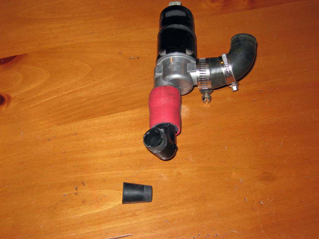
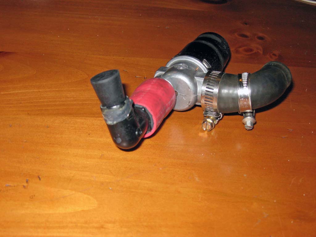
forward. I added a flow restrictor at the idle valve inlet to
limit the air flow into the idle valve so that no more air volume can be
delivered than can be consumed by the engine via the 6mm hoses to the
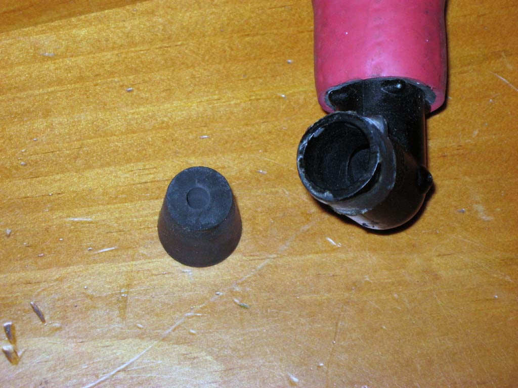
ITBs. I used a rubber stopper that I drilled out to match the
inside diameter of the individual ports on the vacuum manifold.
The rubber stopper was then cut to length and inserted into the inlet of
the idle air valve hose at the intake plenum.
This simple addition to the idle air circuit immediately improved the tuning of fast idle but was not the complete solution. The other piece of the problem involved the issue that my blended tuning tables did not work correctly when the MAP was raised by the idle valve while the throttle position was still fully closed. The solution to this tuning problem is described in the Tuning For Idle Air section of my ITB Tuning page. |
||||||||||||||||||||||||||||||||||||||||||||||||||||||||
This site was last updated 12/29/09