|
|
Ignition Upgrade | |
|
|
Up
|
My original ignition setup using the Ford EDIS control module to drive
the coil pack with the PIP and SAW signals from the MS controller worked
well. I had always wanted to have more direct control over the
coil including dwell control and I also wanted the option of running
four individual coils. When I knew I would have my engine torn
down for the Jenvey TB conversion I decided to pull the engine harness
and MS controller to make the changes necessary for this ignition
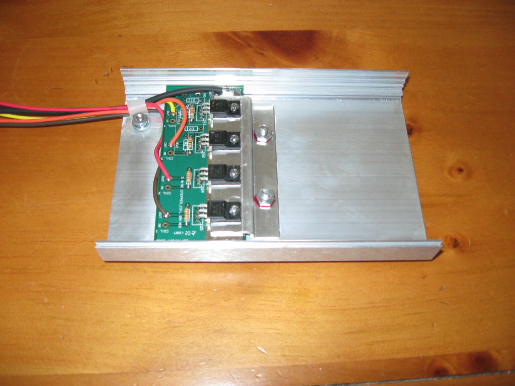
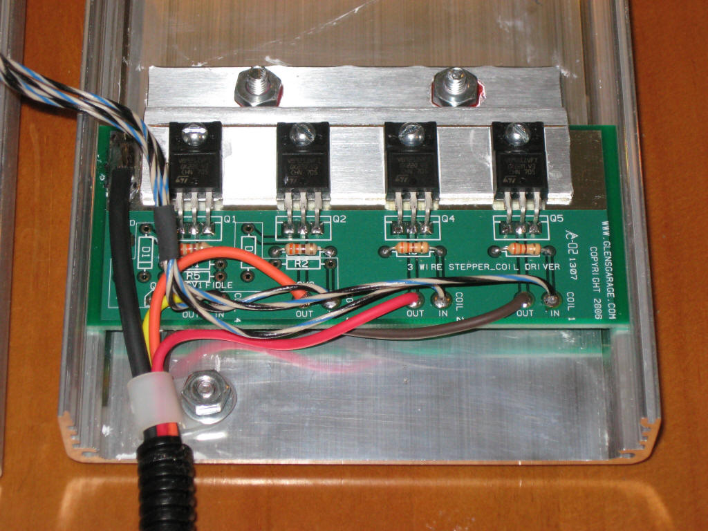
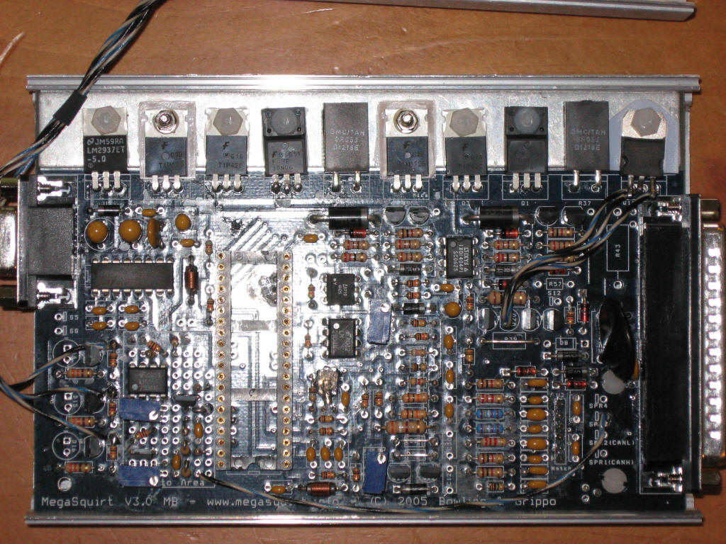
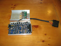
upgrade. I decided I wanted to create an engine harness for the E21 / M10 combination that would provide the flexibility of running just about any ignition option that MS supports. I also wanted to bring out a couple of extra outputs to a connector in the engine bay in case I ever wanted to use them. On the controller side, I needed to add high current drivers for up to 4 coils as well as a second VR sensor input to allow for a cam position sensor. For the coil drivers, I purchased the Ignition Coil Driver Board from Glenn's Garage plus 3 additional VB921 coil drivers. I connected up the coil drivers per the Megamanual and added a separate connector for the high current wires that would trigger the coils. The driver board is designed to mount in the cover of the MS case.
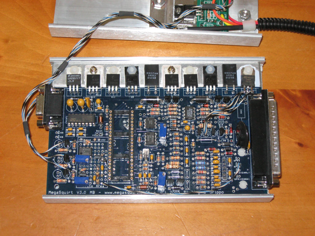
I copied the VR input circuit used on the V3.0 MS main board in the prototype area provided on the board. This circuit was then connected to an unused pin on the MS controller's connector.
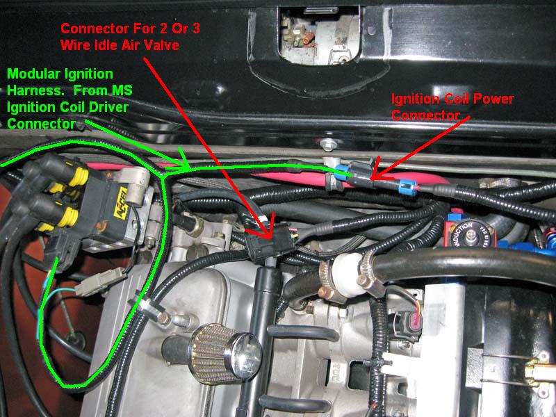
You can also see the power transistor added in the upper right for the PWM idle air valve. For the harness upgrade, I started with my current harness and removed the Ford EDIS portion as well as the current relay and fuse portion. I then upgraded the relays and fuses by adding 2 25A main circuits, one for the ignition coils and one for the rest of the MS system. The MS 25A circuit was then further divided down into individual circuits. An ignition power relay was added that is enabled from the fuel pump relay so power to the ignition is cut if the fuel pump stops. The ignition coil portion of the harness is designed to be modular. The 25A supply for the coils is brought to a connector and the ignition harness mates with this power connector, the coils, and the high current connector on the MS controller. Connectors for a PWM idle air valve and a connector to allow selection of the tach input signal were also added. Here is the engine harness diagram for this newer version of the harness. A picture showing the locations of the IAC connector, the ignition coil power connector, and the routing of the ignition harness. The ignition harness can now be swapped out to change from wasted spark to 4-coil without effecting the rest of the engine harness.
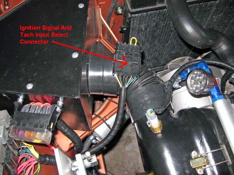
This ignition signal and tach select connector allows selection of multiple tach sources for both Megasquirt and the tachometer. The yellow jumper currently installed sends the MS tachout signal to the tachometer. This connector would allow other external signals to drive the tachometer if needed. There is also a low current power supply pin in case +12V was needed for some reason.
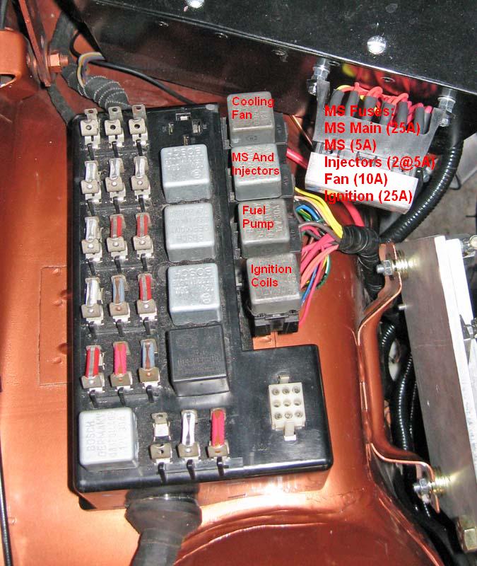
Locations of the 4 additional relays used to control the power to the cooling fan, Megasquirt, fuel pump, and ignition system. The MS fuse block has 6 fuses:
|
||||||||||||||||||||||||||||||||||
This site was last updated 12/29/09