|
|
Distributor Cam Position Sensor | |
|
|
Up
|
This is a side project that I started during the summer of 2008 as an
experiment to see if I could come up with a way to add a cam position
sensor to the M10 engine. I wanted something that any DIYer could
do without the need for machining or welding. This limitation
pretty much removed the options of adding a hall or VR sensor directly
to the cam as this would involve going through the valve cover or timing
cover in some way. This cam position sensor was tested on my
engine and found to operate in that it produced a cam position pulse as
expected. I never used this sensor on my car and instead decided
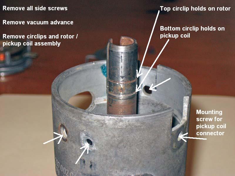
to go with a hall effect sensor through the timing cover. It occurred to me that the late model E21 used an electronic ignition with an impulse sender built into the distributor. I did a little research and verified that the impulse sender was just a VR sensor that sent a pulse for every spark event. I started investigating what it would take to turn this mechanism into a VR sensor that would send only one pulse every crank revolution. This first problem turned out to be pretty easy to solve. You just need to cut off 3 of the 4 metal tabs on both the pickup coil and the rotating part of the impulse sender. Another more complicated problem was that the impulse sender was designed to change position with the mechanical and vacuum advance mechanisms. These mechanisms would need to be locked down so the impulse sender would not change position and thus change the timing of the cam position signal. I first took a late model E21 distributor completely apart and started playing with it. Here is what I came up with. Some information on removing the impulse sender components from the distributor
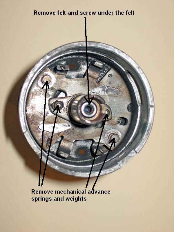
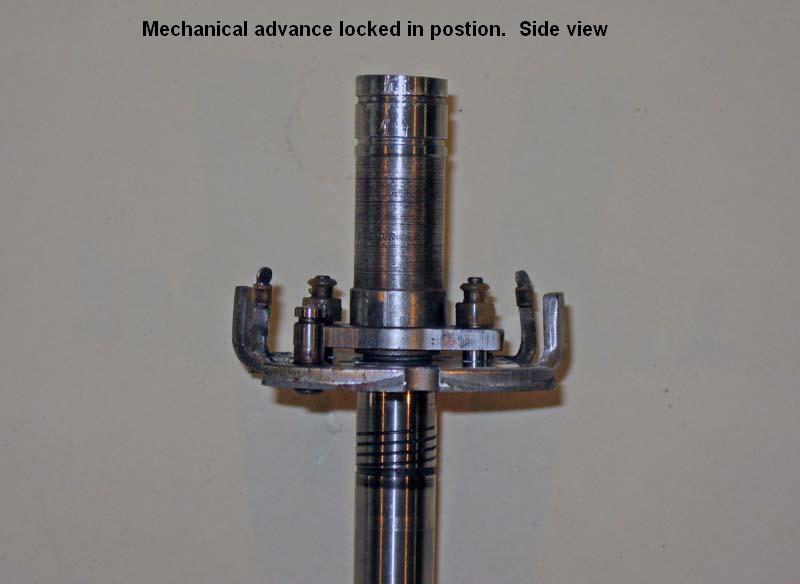
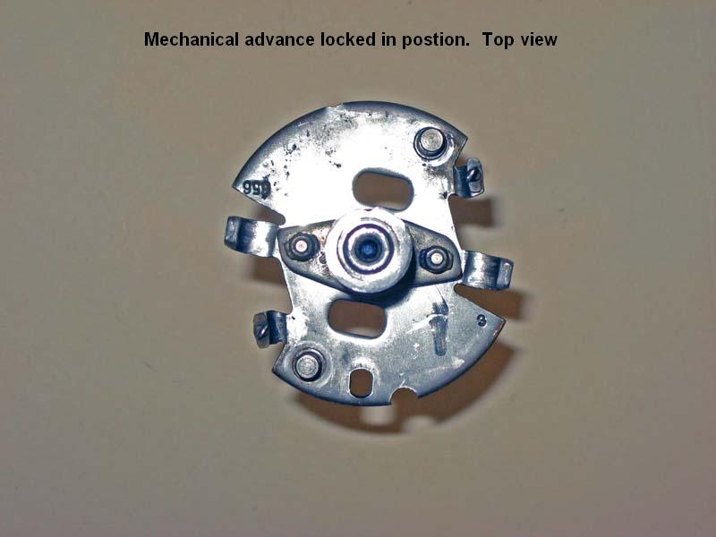
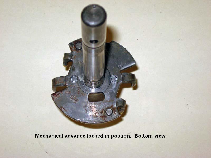
Removing the mechanical advance
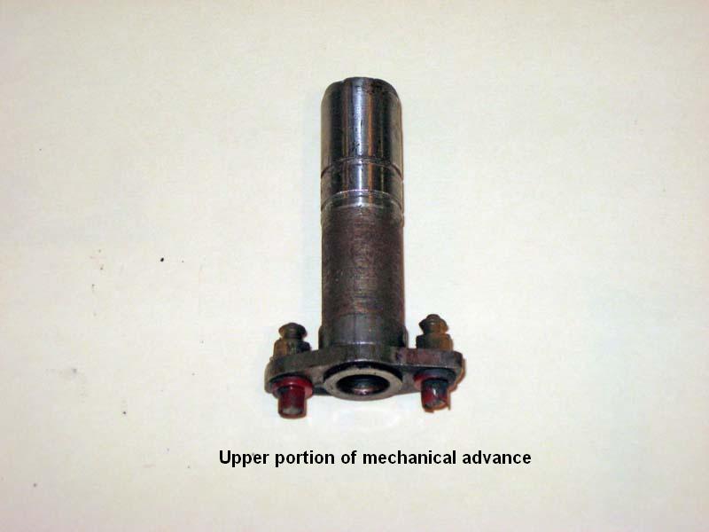
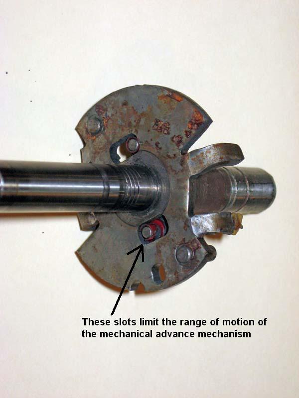
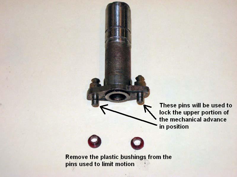
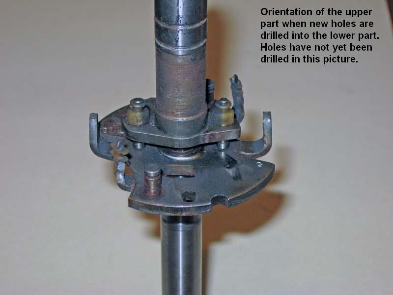
Details of how the mechanical advance goes together
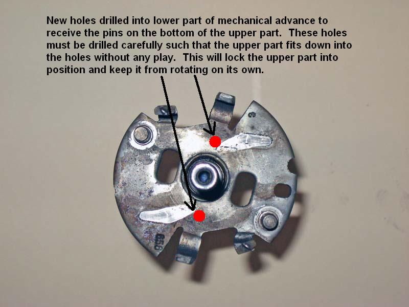
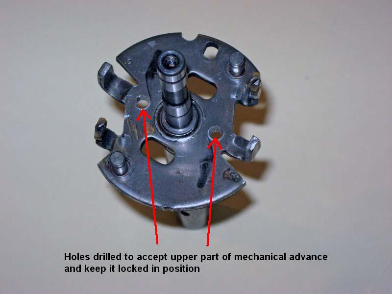
The way to lock the mechanical advance is to drill a new set of holes in the lower part that will receive the pins from the upper part and keep it from rotating
I put a drop of white paint on the bottom of each pin and carefully place the upper part back on its shaft so the wet paint marked where I needed to drill the holes.
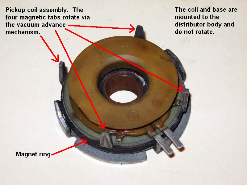
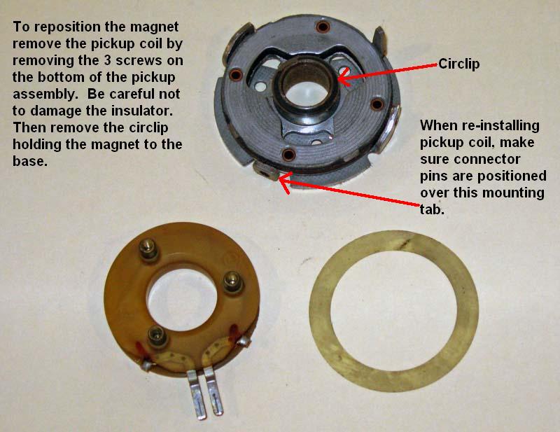
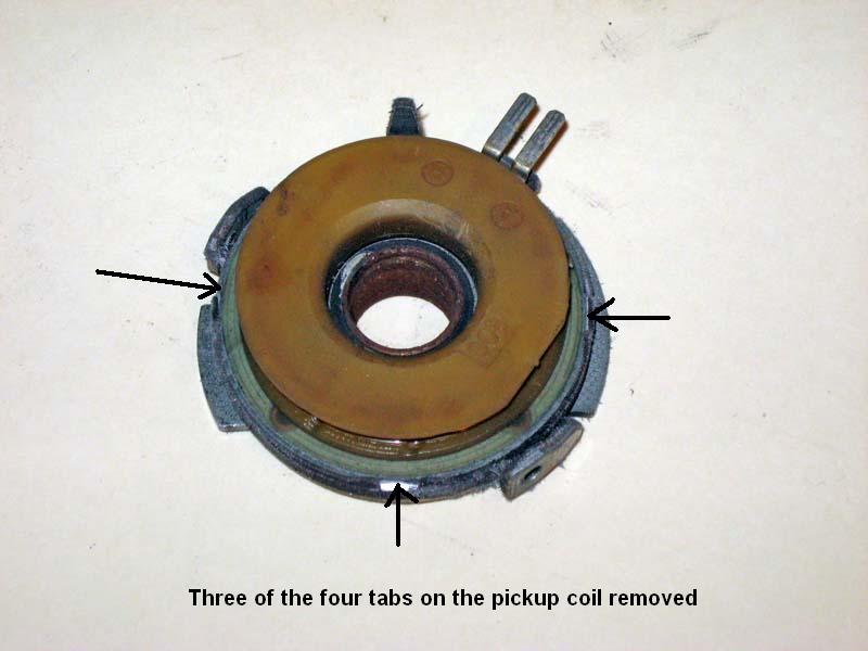
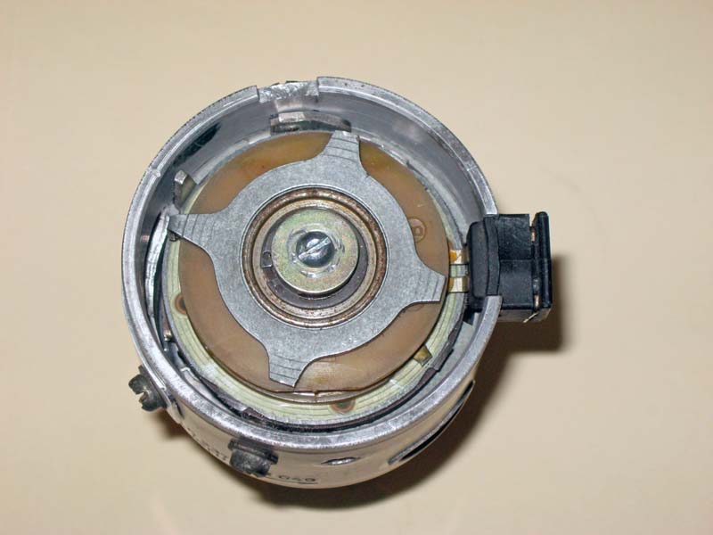
Details of the pickup coil assembly
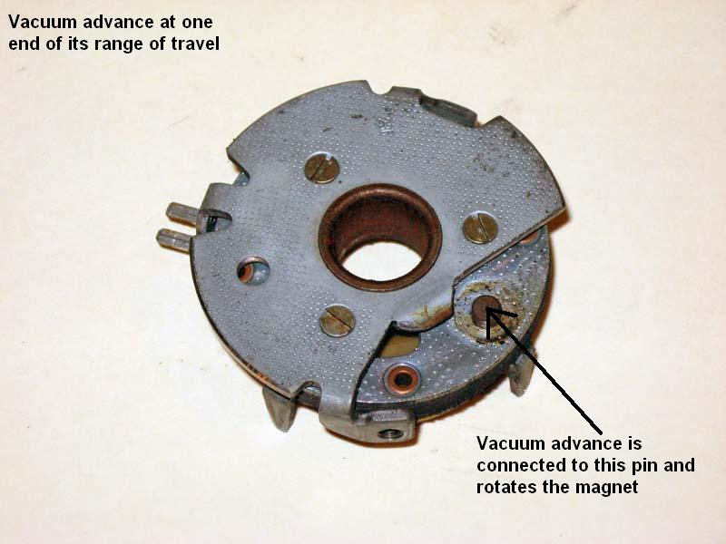
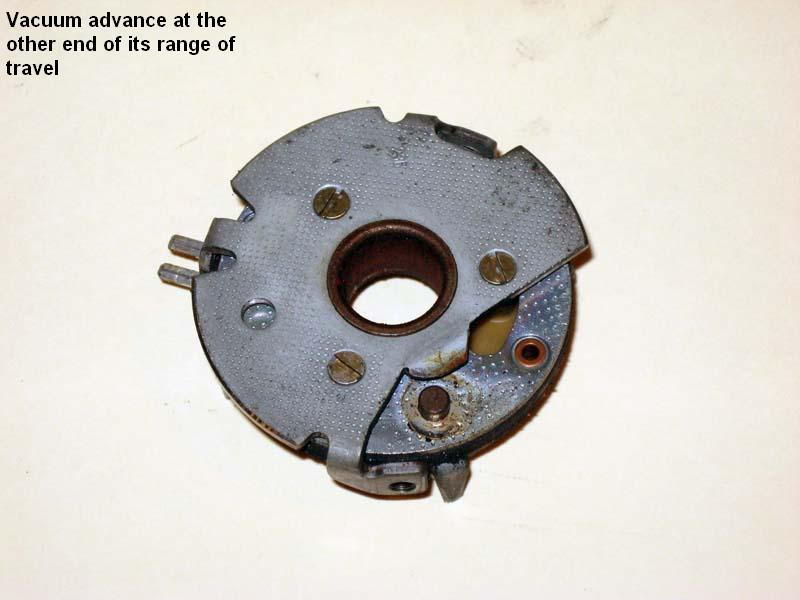
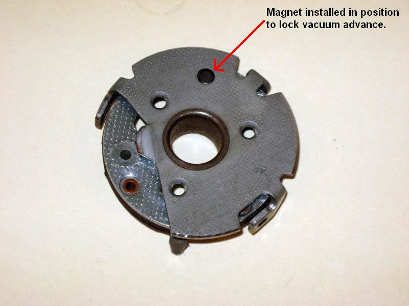
How the vacuum advance mechanism rotates
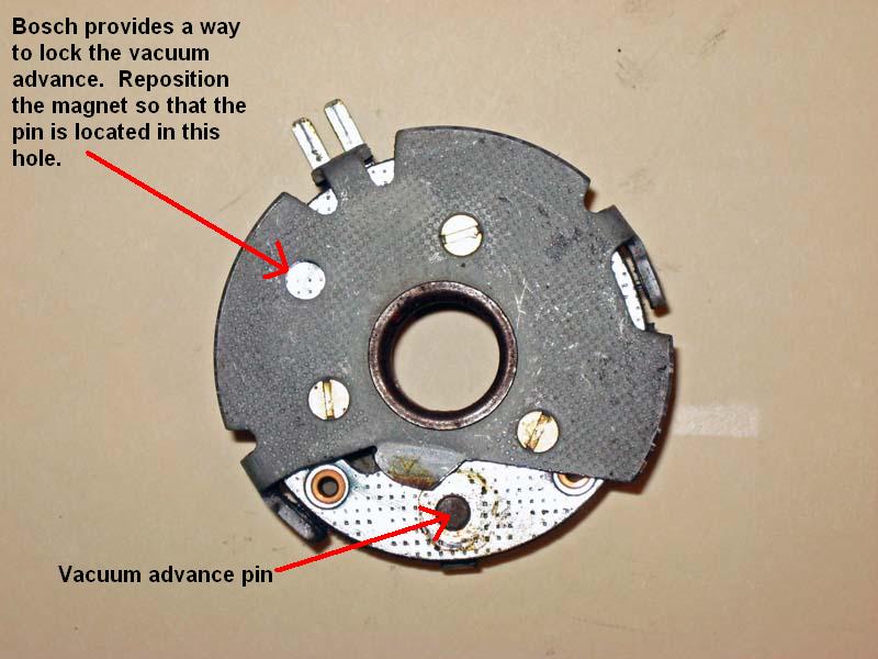
I noticed that extra hole in the bottom of the impulse sender assembly and wondered if the pin for the vacuum advance would align with it. When I tried this I was pleasantly surprised that it looks like Bosch had provided this hole for the express purpose of locking the impulse sender advance mechanism. All I needed to do was take the impulse sender apart and re-assemble it with the pin in the hole
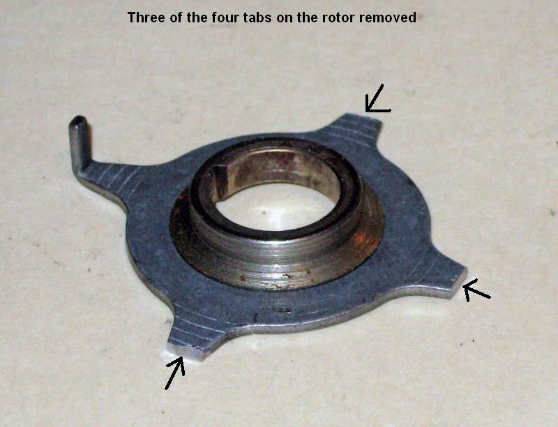
To only send one pulse per revolution you need to cut off 3 of the 4 tabs
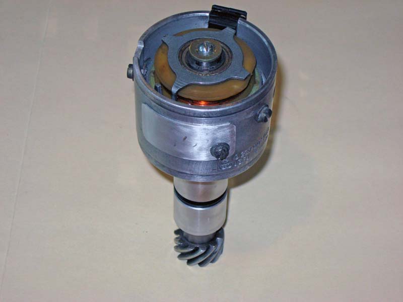
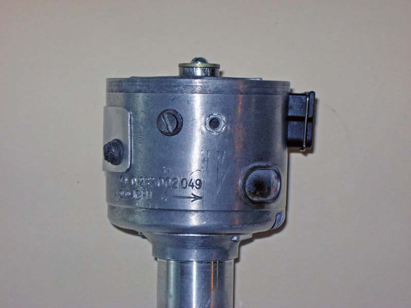
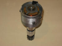
I then cut down the distributor shaft to remove the upper half inch or so that used to hold the rotor. The distributor was then re-assembled. I used a drive gear from a 2.0L engine since the early and late model distributors were driven in opposite directions.
I also fabricated a simple cover for the vacuum advance hole. I installed this on my engine and verified that it provides a pulse once per crank revolution. I still need to fabricate some kind of cover for the top if this. I could just put a distributor cap on it but I don't want to do that. This is now sitting on a shelf waiting for me to work on a coil-on-plug upgrade.
|
This site was last updated 03/31/10