|
|
Cam Position Sensor | |
|
| Up |
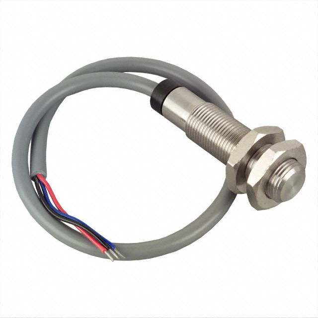
In order to convert my Megasquirt system to sequential injection and
spark I needed to add a cam position sensor to my engine. The job
of the cam position sensor is to identify when the missing tooth on the
crank trigger wheel is for cylinder #1. The simplest timing setup
for a Megasquirt cam position sensor is to produce a single cam position
pulse at least one crank wheel tooth prior to the crank wheel missing
tooth. This is the approach that I took. I wanted a way to
produce a pulse once per cam revolution that was timed to occur a few
crank wheel teeth prior to the crank missing tooth.
My first attempt at a cam position sensor was to modify a distributor with electronic pickup to produce this pulse. This first attempt is linked to on the left side of this page. I managed to create a working sensor this way but was never happy with the way it looked on the engine and decided not to use it.
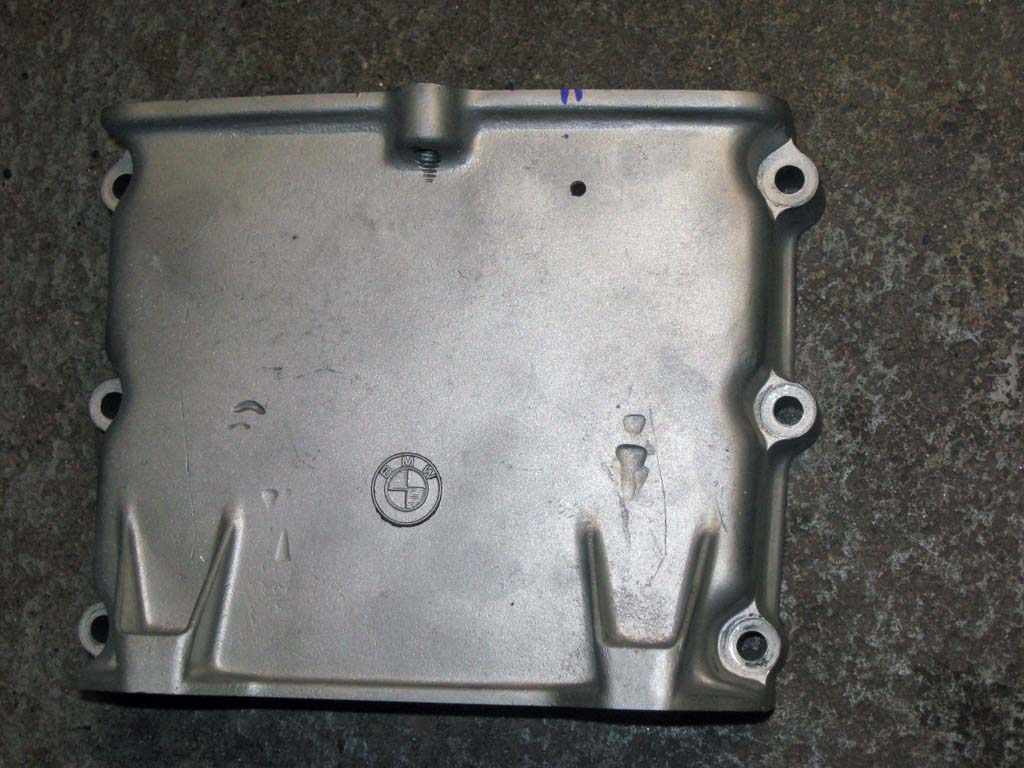
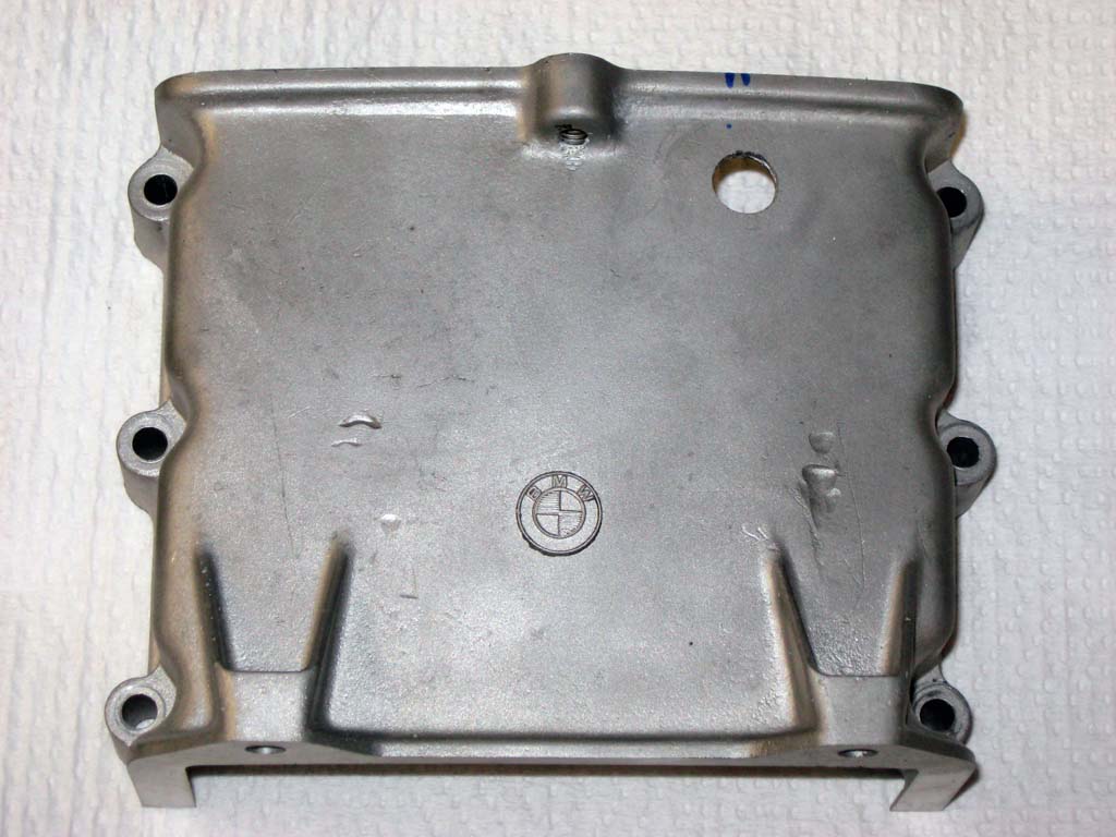
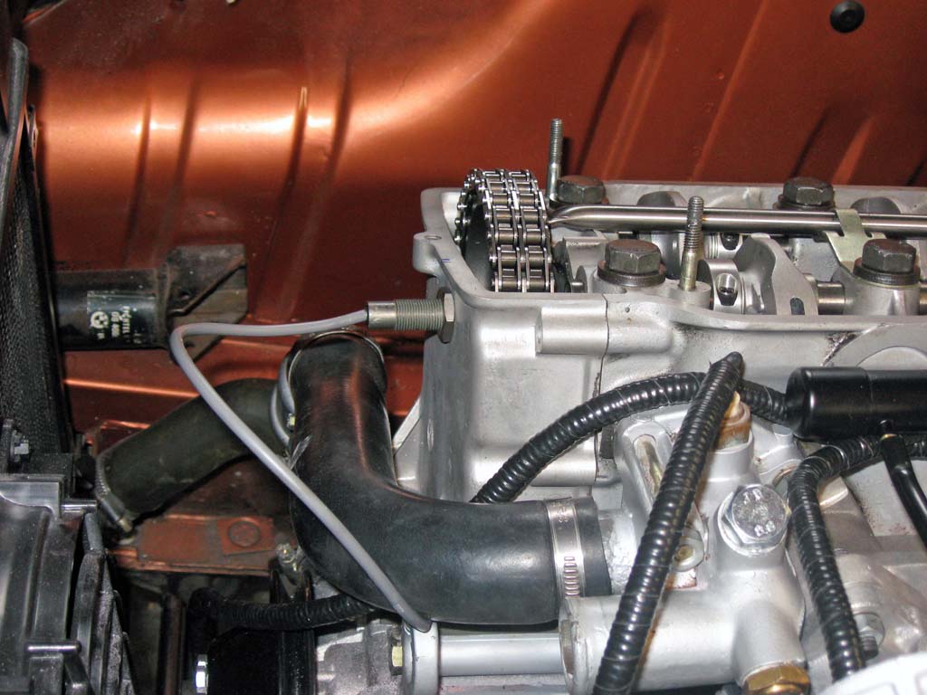
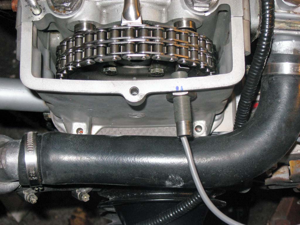
With a suitable sensor located, I had a spare upper timing cover milled to match the height of my cylinder head. I did not want to chance ruining my upper timing cover without having a spare available.
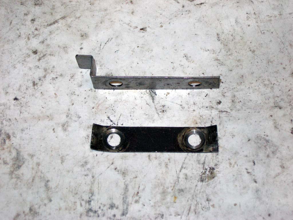
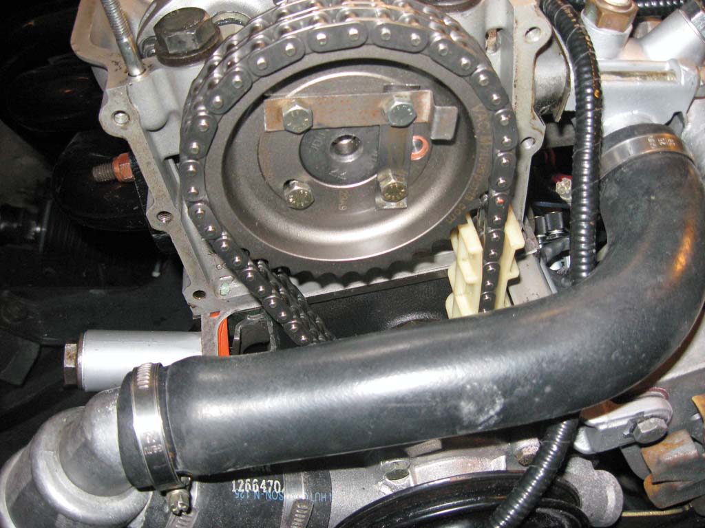
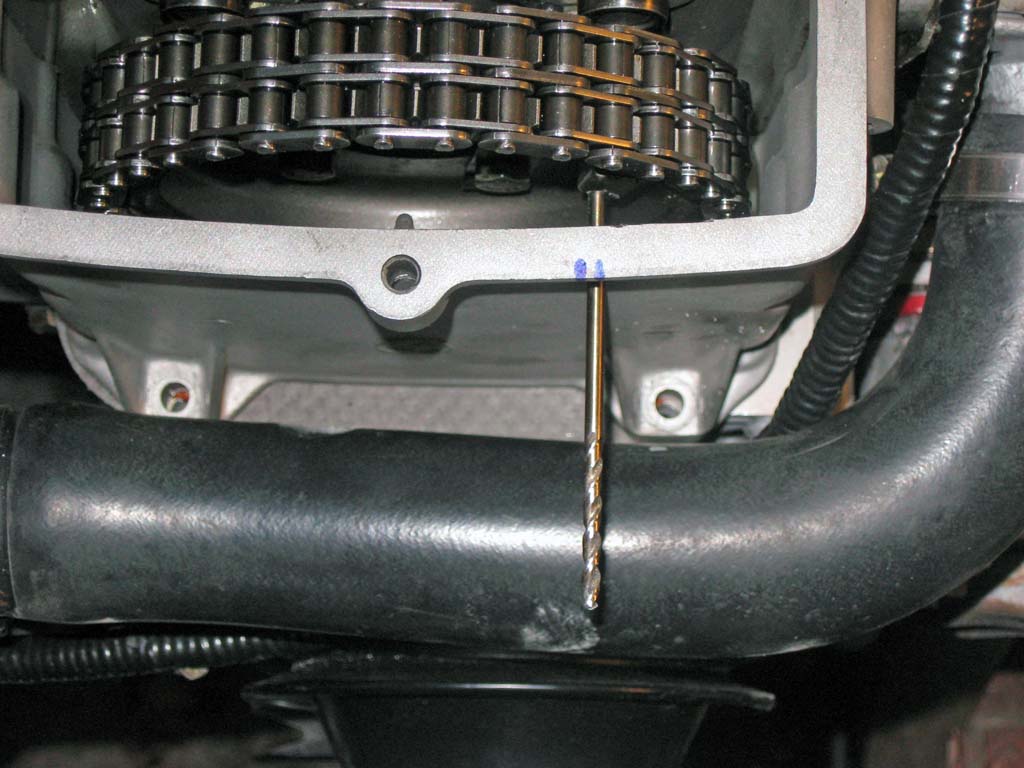
Then it was a straight forward process of locating the correct place to drill the hole for the sensor. The sensor location is a one shot deal so you need to ensure the proper timing relationship between the cam flag and crank trigger prior to drilling the hole!
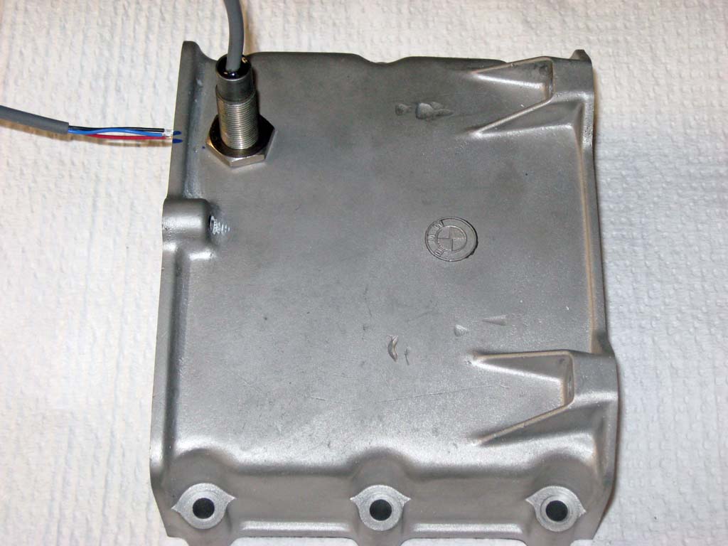
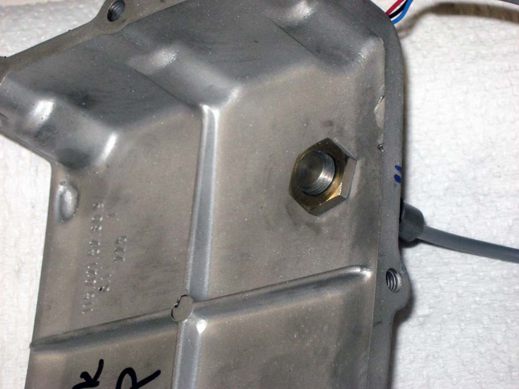
Final installation of the sensor was done using a liberal amount of red loctite to prevent the inside jam nut from loosening and to seal the sensor hole against oil leaks. The timing cover is only a few millimeters thick so you need to be careful not to crack the case my over-tightening the sensor nuts.
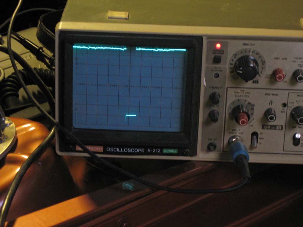
The cam position sensor is functional and ready to go. As soon as I get my MS3x board that contains the separate injector drivers and cam position sensor conditioning circuit I will be all set for sequential. |
|||||||||||||||||||||||||||||||||||||||||||||||||||||||
This site was last updated 03/31/10