 |
EFI Harness | |
|
|
Up
|
There are several ways to approach the wiring required for a MS
conversion. One common solution is to use the
MS Relay Board. This board provides a single location where
all the wires are connected as well as the relays and fuses required. Here is a wiring diagram showing a typical MS installation. I personally did not like the relay board solution. It would not look right in my engine compartment and I did not like the use of screw terminals to connect all the engine wires. This is a personal preference and not a design problem with the relay board, many people use the relay board without any problems. I have had two major harness building projects. The first harness was built to use the Ford EDIS control module and run a basic MS2 setup. When I converted my fuel system to the Jenvey TBs I also upgraded my MS2 controller as well as the engine harness. This upgrade involved removing the Ford EDIS controller and directly controlling the ignition system from the MS2 controller. I also made several other improvements to support additional features. This second generation of engine harness is described in detail on the Ignition Upgrade page. 1st Generation EFI Harness I decided to build a custom engine harness that would plug into the OEM engine harness connector on the fuse box and completely replace the original Kjet engine harness. The first generation of this harness was made to use the Ford EDIS control module to control the ignition system based on control signals from the MS controller. What I call my 1st generation harness was used for the EDIS only with carb setup as well as with the TWM ITBs that were used in my first EFI fuel system. Here is a .pdf file that contains the electrical diagrams for the modified engine harness as well as the harness layout diagram that shows all the lengths for the engine harness. You will need Adobe Reader to view this file.
My personal preference when laying out a new harness of this complexity is to mock up the harness in place first. I do this by using lengths of weed eater line and wire ties to figure out the harness routing and lengths. Once this harness mock up is laid out I carefully remove it and use it as a template for the actual harness. A very important consideration in laying out the engine harness was to keep the VR sensor wires for the crank position sensor away from the high voltage ignition wires as well as the alternator and starter.
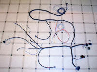
Here is a picture of the completed harness laid out on my kitchen floor prior to install. I purchased the universal harness kit that RS Autosport sells. I purchased most of my connectors from them as well. I got some extra wire required for the EDIS portion of the harness from KayJayCo Automotive Electrical Supplies. Only GXL grade wire was used. All sensor lines are run as twisted pairs with their own ground return. All sensor twisted pairs were then run inside 1/4 tinned copper ground braid. All sensor and shield grounds are terminated at the MS ground to prevent ground loops. The entire harness was then wrapped with high temp nylon convoluted tubing which was then sealed with a wrap of black electrical tape. All connector terminals were crimped and soldered. No pigtails used in this harness. A little extra expense and time spent at this stage should prevent sensor noise problems down the road.
This first install of the harness was for the ignition control while using carbs. The fuel injector, TPS portion of the harness was left unterminated at this point waiting to be finished when the ITBs were installed. I ultimately did not use a stepper motor idle control and the wires for the stepper motor IAC were eventually used for other generic outputs. Here are some pictures of this first install. I used OEM relay connectors clipped onto the side of the fuse box to mount the new relays. One relay for the electric radiator fan is not installed yet in these pictures. Notice the Ford EDIS control module is mounted out of the way under the battery tray. The extra fuses were also mounted under the battery tray with the EDIS module.
|
||||||||||||||||||||||||||||||||||||
This site was last updated 12/29/09