|
|
Coil On Plug Ignition | |
|
|
Up
|
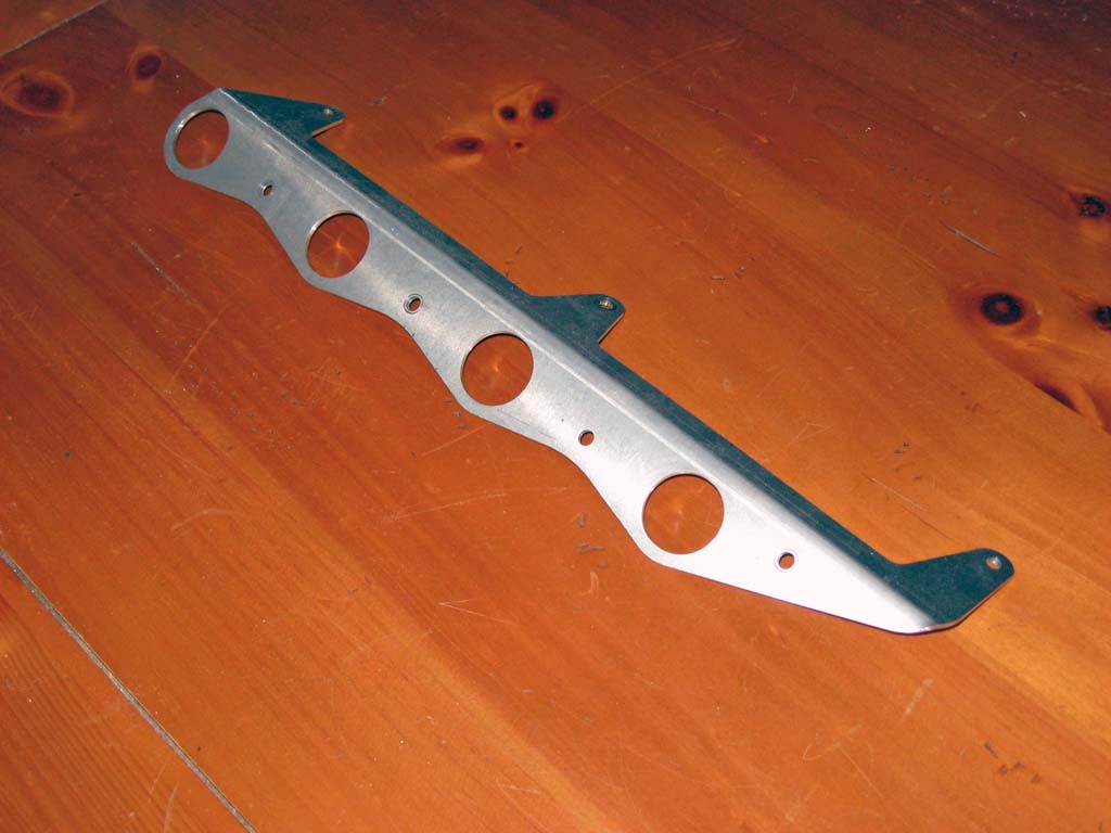
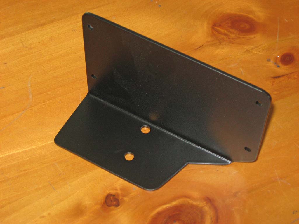
Coil Harness | First Prototype | Second Prototype | Electrical Interference | Second Coil Harness Attempt | Ignition Control Box A coil on plug (COP) ignition setup has been on my list of things to do for a couple years now. I first got the idea for this from Tim's Megasquirt Project. He figured out that you could use the coils from a late model BMW and drive them in wasted spark configuration from the Ford EDIS ignition control module. Details of this are on Tim's web site. My intended use of a COP ignition was to directly control the coils from my Megasquirt controller instead of the EDIS controller. I intended to wait until I could run fully sequential injection and directly fire the coils independently so this project was a little ways down on my list. In early September I was contacted by Tom from www.02again.com and asked if I wanted to work with him on developing a mounting bracket to allow a similar COP setup (he had also seen Tim's setup). I had not planned on starting this project but when presented with an opportunity like this, I could not refuse. Over the next 4-6 weeks we developed the concept from an initial prototype that Tom had already fabricated into a final design that works very well on the M10 engine. This page details the development of this COP setup from initial prototype through to final parts. The coil mounting bracket is a future product from 02again and should be available in the near future. Here is the original prototype coil mount bracket that Tom sent me to try out.
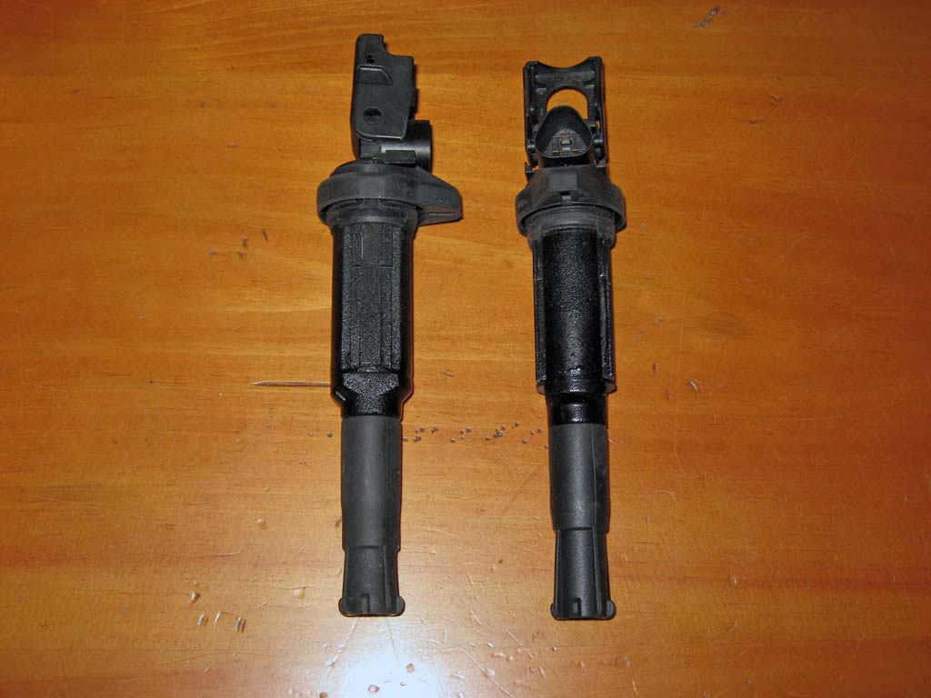
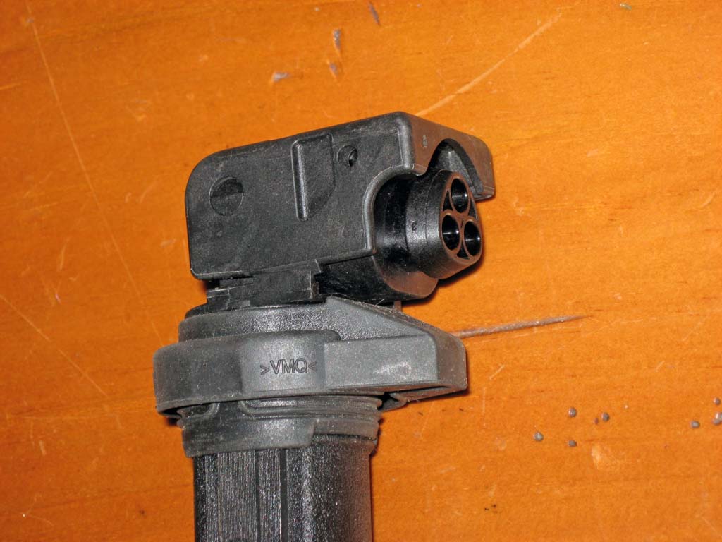
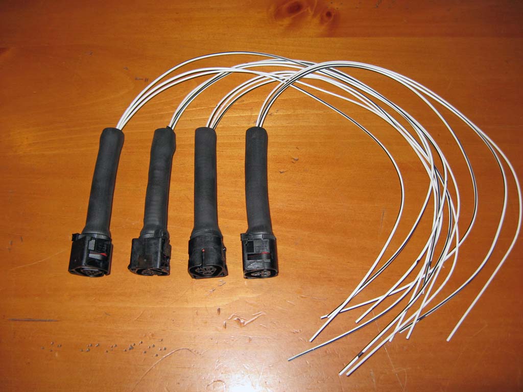
Before I could convert my wasted spark coil pack ignition to COP I needed to fabricate a new ignition harness. I had already planned on this option a couple winters ago when I did my Megasquirt ignition upgrade project. During that project I had installed four high current coil drivers into my Megasquirt controller and had modified the engine harness to accept different ignition coil harness configurations. The coils used for this project are used on almost all late model BMWs from about 2002 onward. There are two BMW part numbers for two different coils that will work:
These coils are available from most auto parts stores for anywhere from $25 to $65 each so you will want to shop around for the best price. I cross referenced the part numbers and used a 2004 BMW 330i sedan as the car for the parts store to reference.
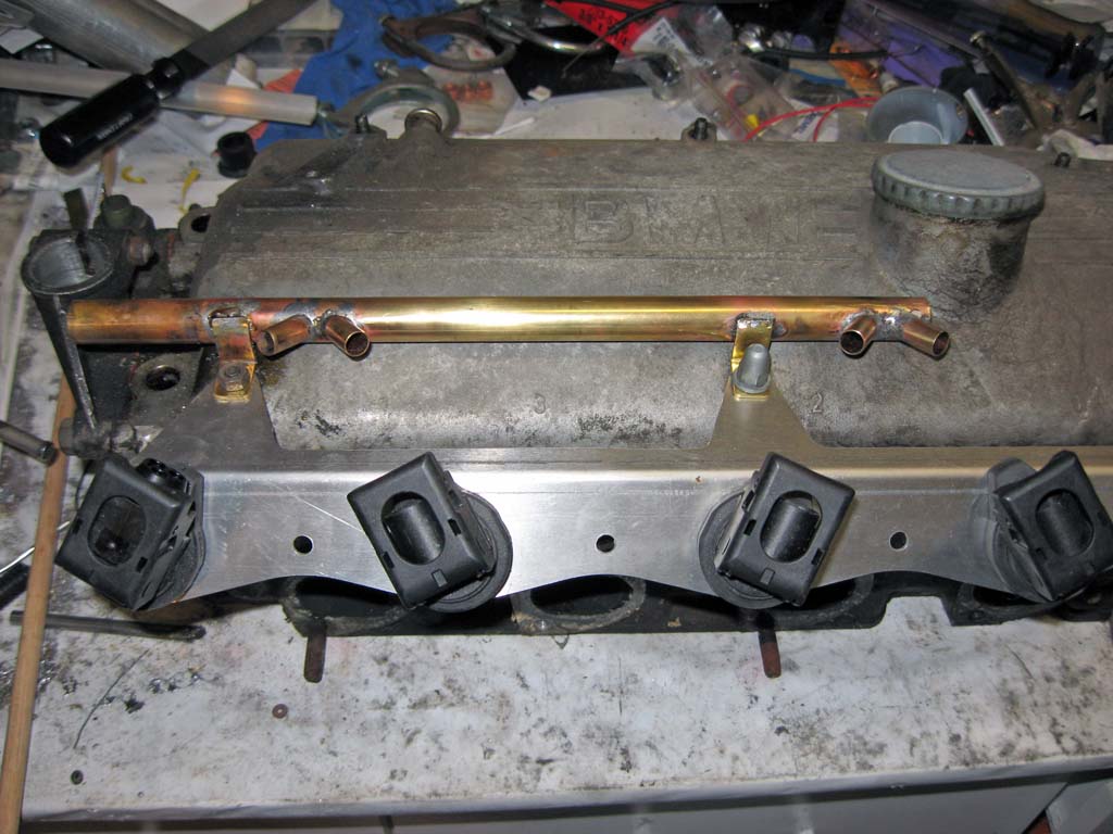
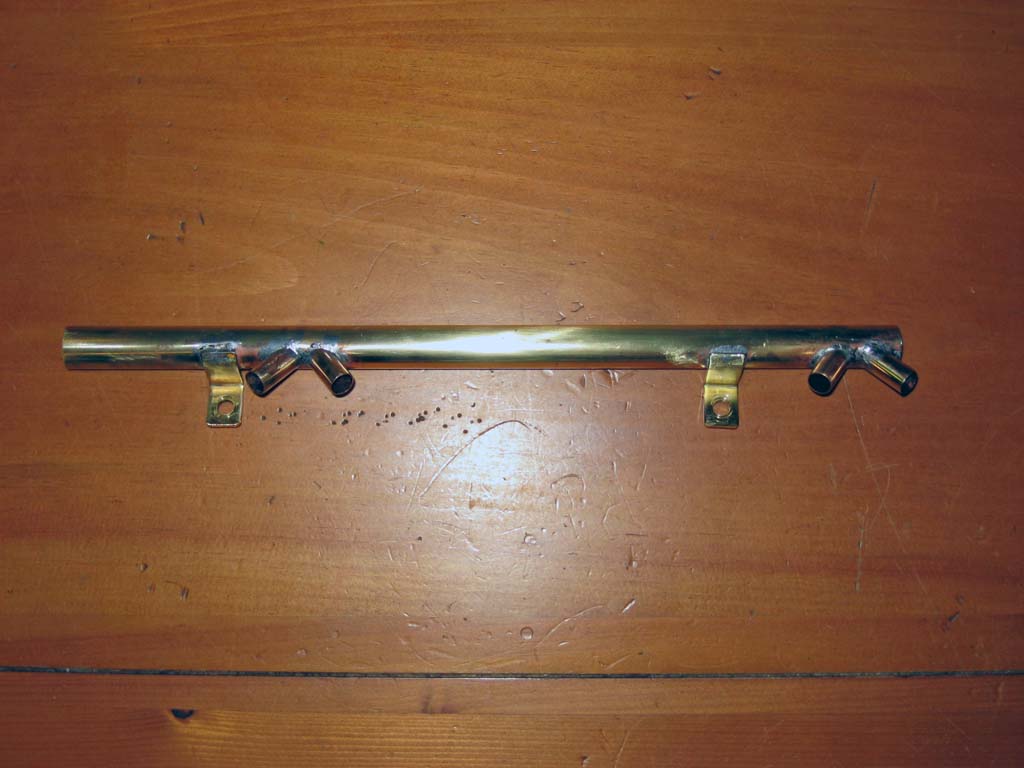
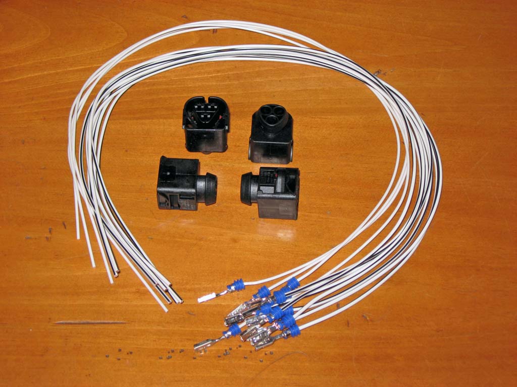
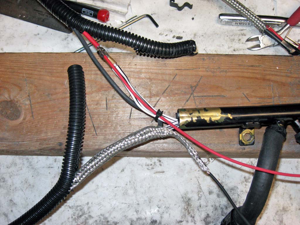
I fabricated a wire holder for the ignition harness out of some brass tubing. This kind of tubing is normally found at hobby shops or arts and crafts stores. I soldered the holder together using regular plumber's solder and flux. Here is a drawing of this holder. I ordered a set of mating connectors and pigtails from my BMW dealer. The BMW part numbers I used are:
The cost of these parts was about $50. A full wiring diagram for my coil harness is here. I used the thinner gauge wires for the ground connection on pin4a of the coils. The heavier gauge wires were used for the coil (+) and coil (-) connections. The coil ground wires were terminated to a ring lug that is attached to the coil mounting bracket.
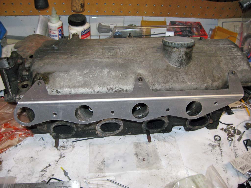
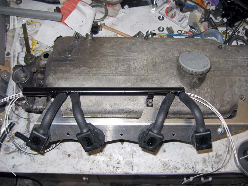
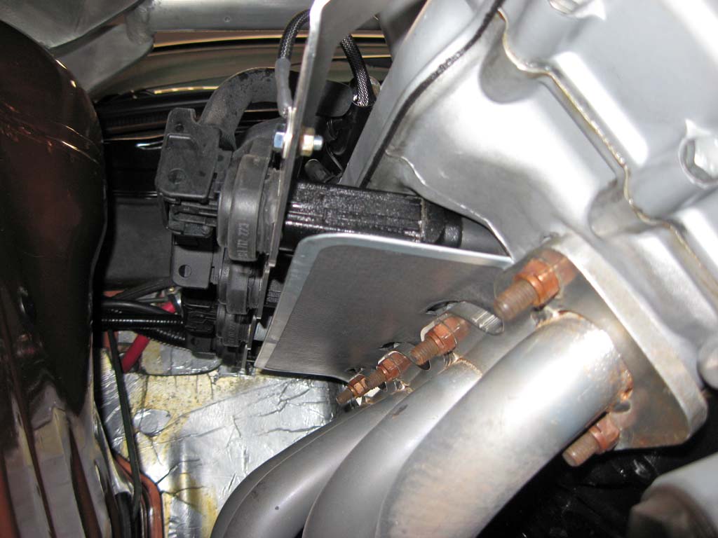
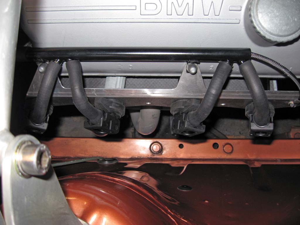
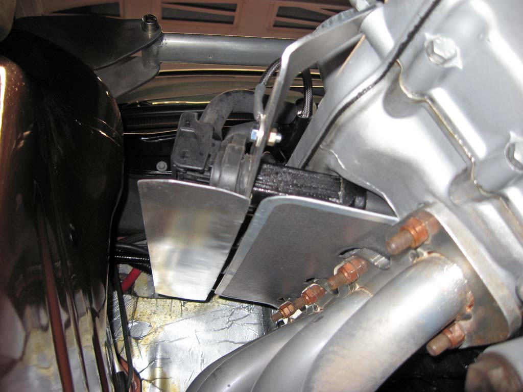
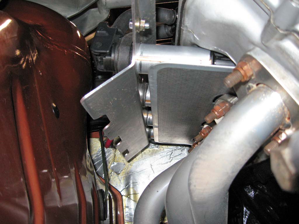
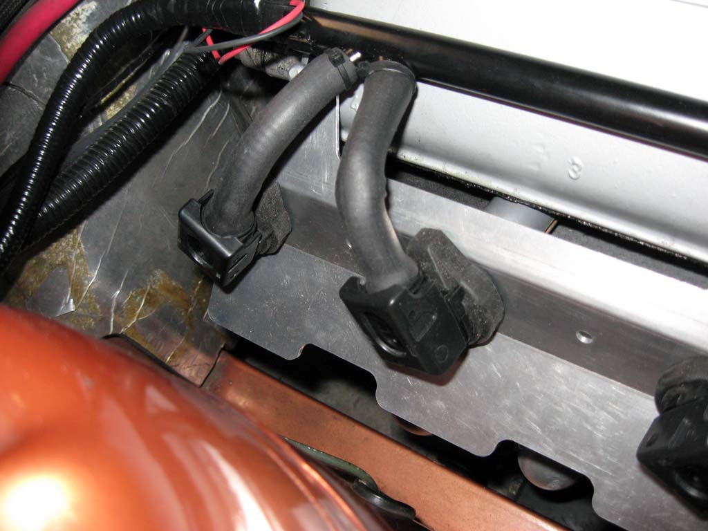
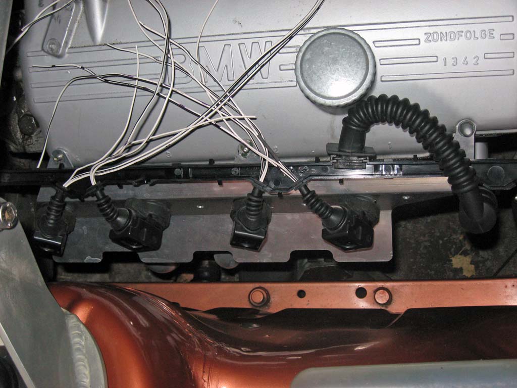
Once I had the harness modified, the COP setup with the first prototype bracket when together pretty easily. A few issues were identified. The most significant issue was that the runners from my header extended out from the block fat enough to be located directly under the tops of the coils and extended out beyond the heat shield of the exhaust gasket. Within a few minutes of idling the engine, the coils were too hot to touch.
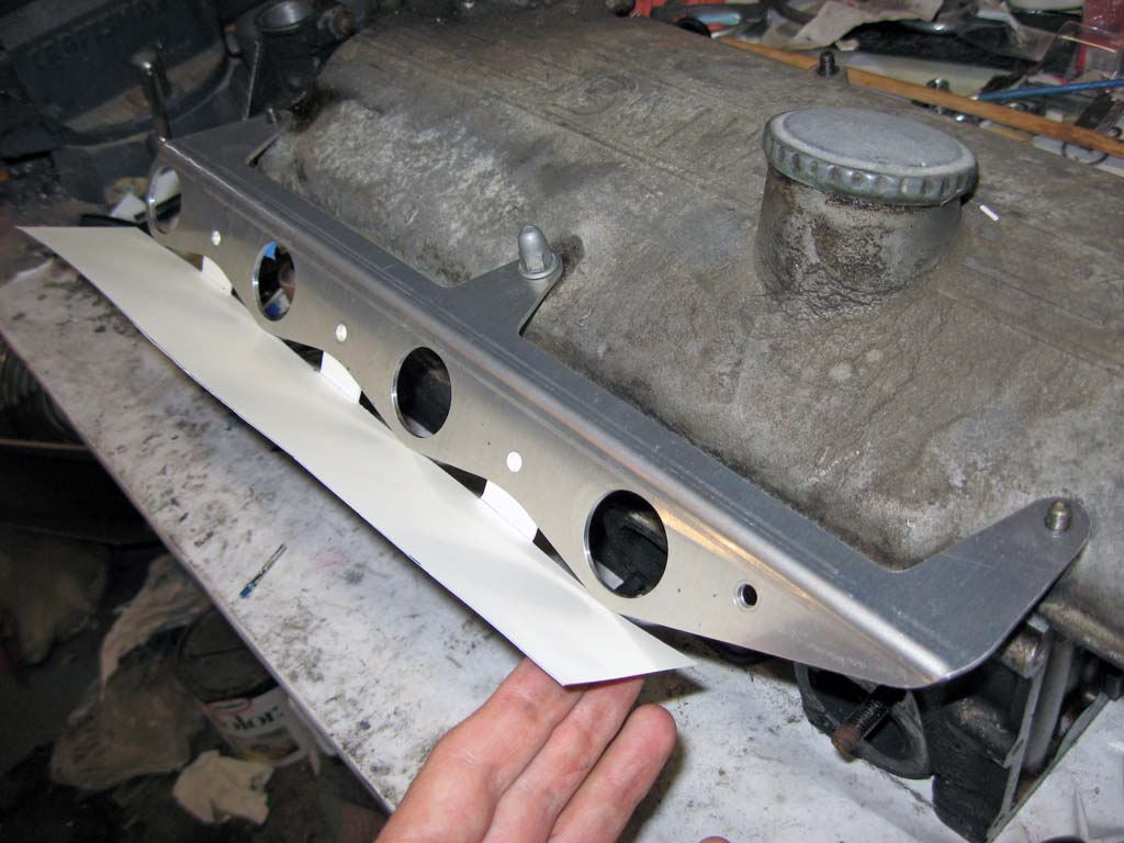
Issues Identified With First Prototype I fabricated a simple extension to the heat shield out of some sheet aluminum and attached this extension to the prototype bracket. This solved the problem with cooking the coils. I was able to drive the car for over an hour and pop the hood and grab the coils without any difficulty.
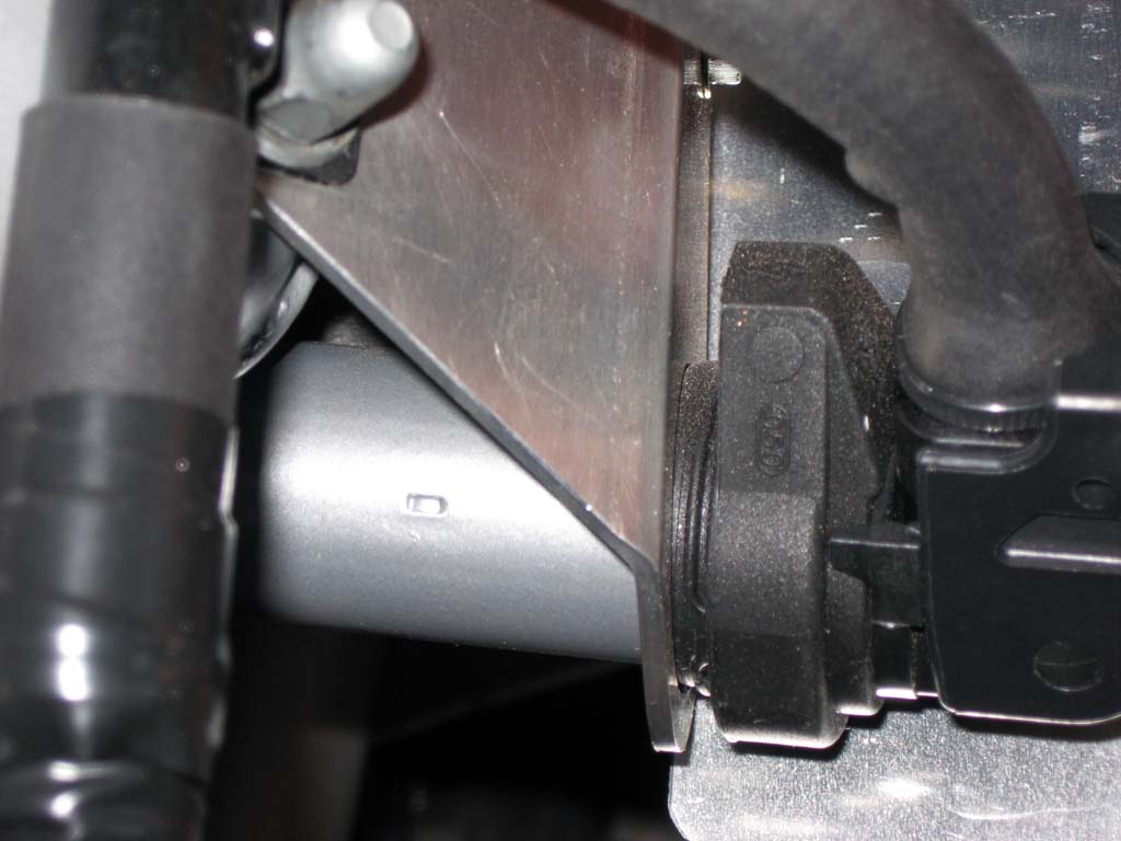
Another minor issue with the first prototype was that the bracket needed to extend out about another 1/8 inch to allow the coils to properly seat in the bracket.
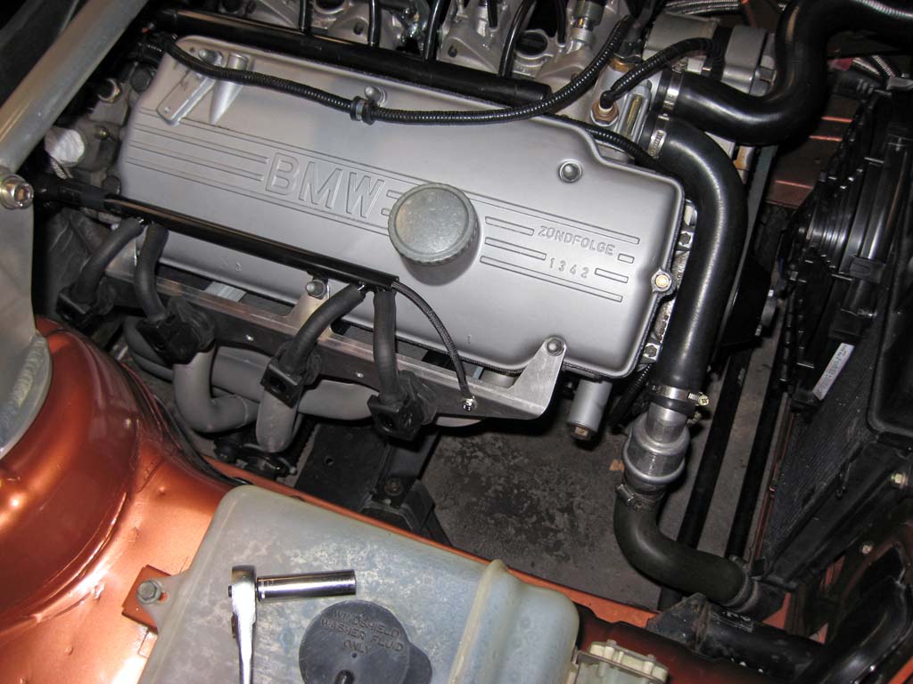
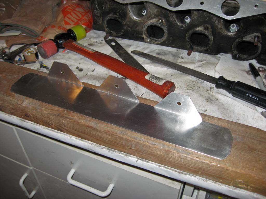
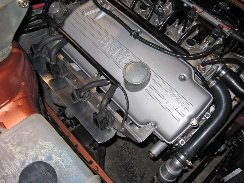
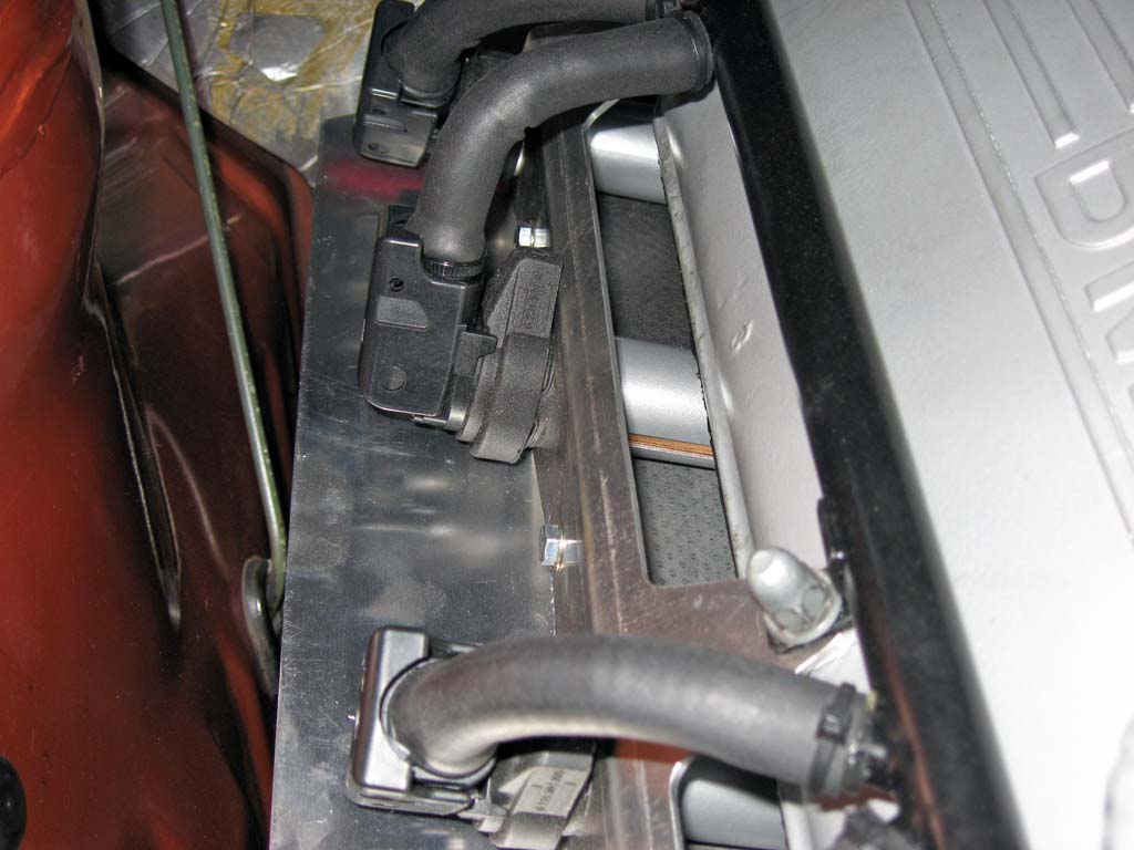
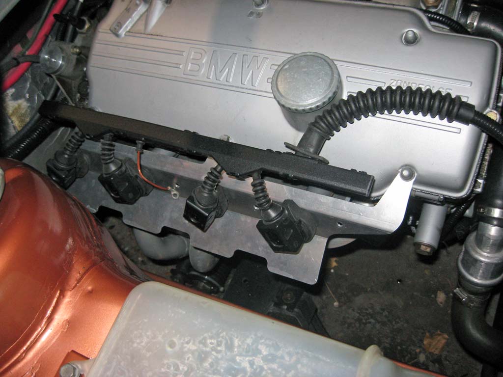
I provided all this feedback to Tom and after a couple weeks he had a second prototype out to me with all the improvements I identified. He integrated the extended heat shield into the bracket design and adjusted the bracket dimensions to correct the coil fitment issues.
The most significant problem I encountered ended up being electrical. I had mounted my high current coil drivers inside the Megasquirt controller's case and I think this was a mistake. The electrical noise generated by the four high current drivers as well as the electrical noise transmitted back from the coils into the controller's case cause significant electrical noise problems. When I initially started driving with the COP setup, I lost my serial communications and experienced several lost sync events and even a couple reboots of the controller. The noise was so bad that my TechEdge wideband O2 controller crashed and needed to be re-flashed to recover. I identified the electrical noise problem by switching my car radio over to AM and was immediately able to hear the noise which changed pitch with engine RPM (ignition noise). I addressed this noise problem with several modifications to my ignition harness. These changes were:
The combination of these changes have eliminated the electrical noise problems. (My AM radio reception is also fixed...)
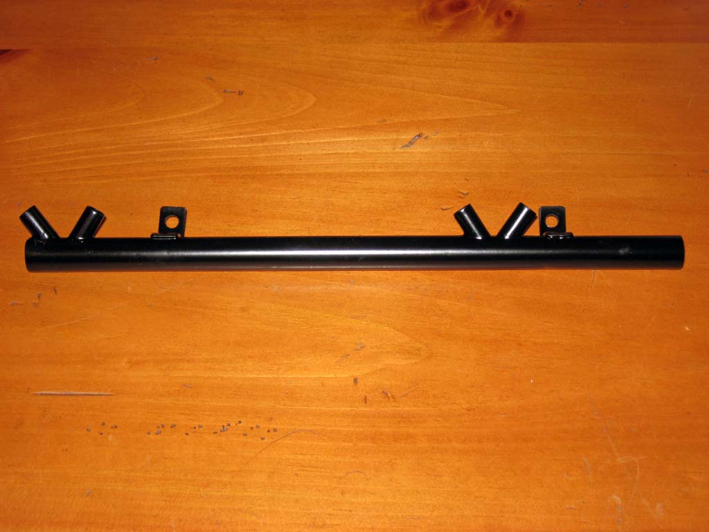
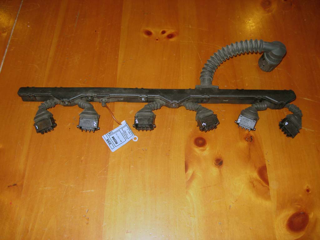
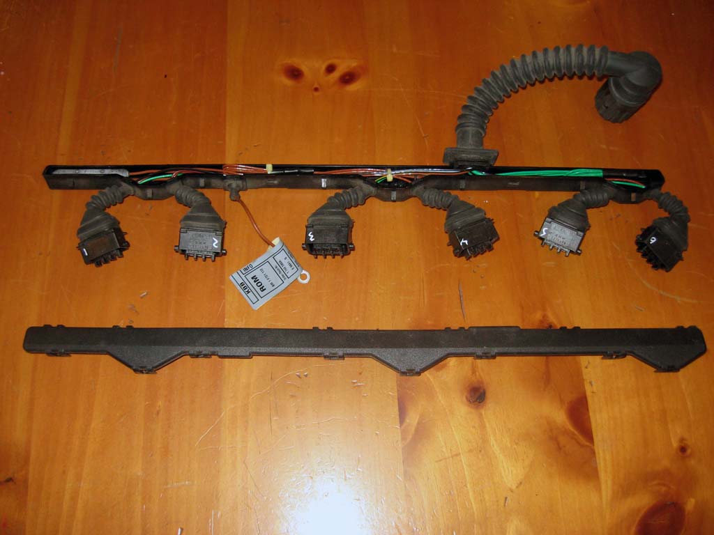
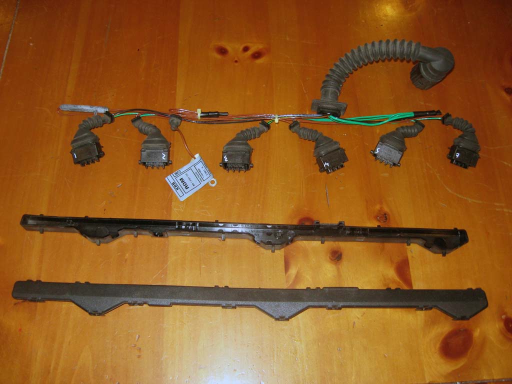
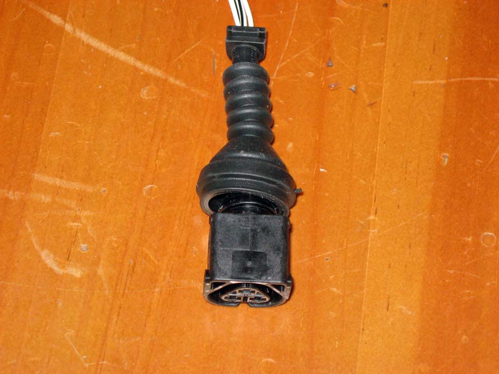
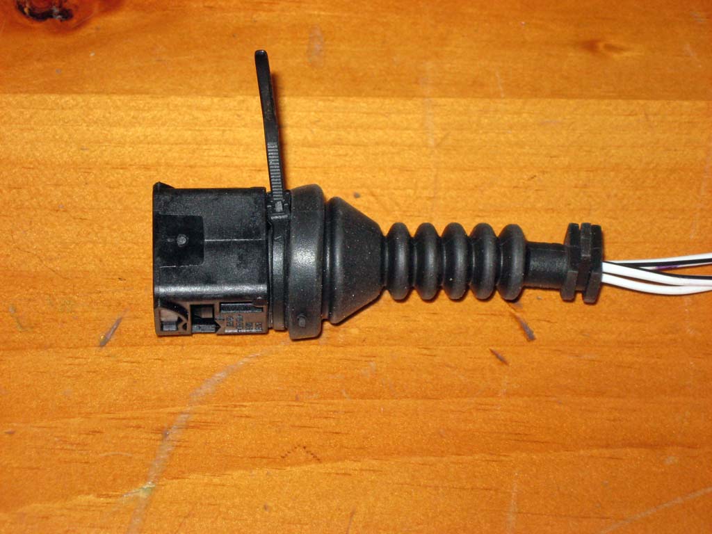
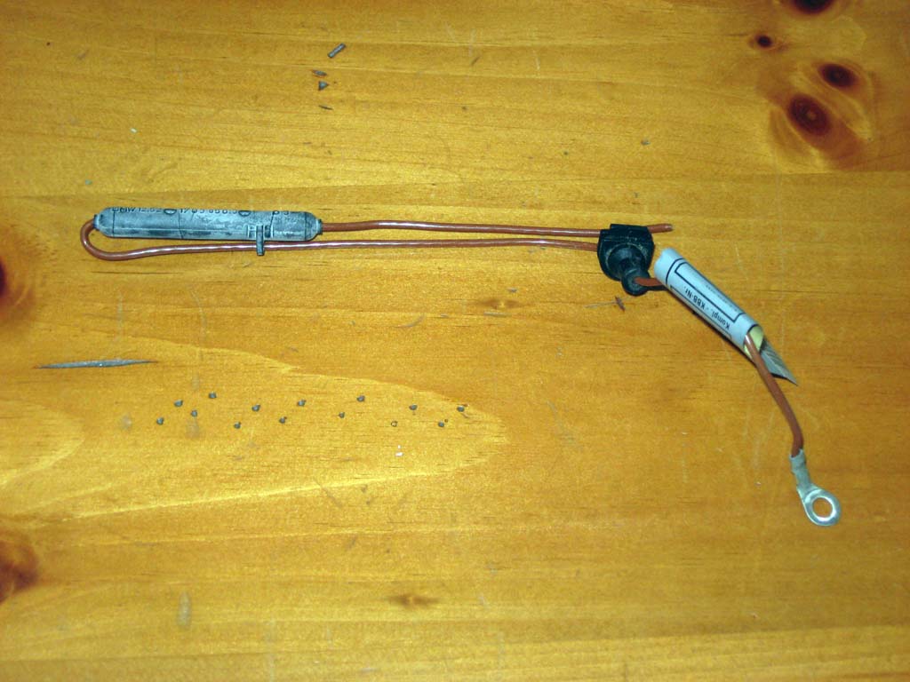
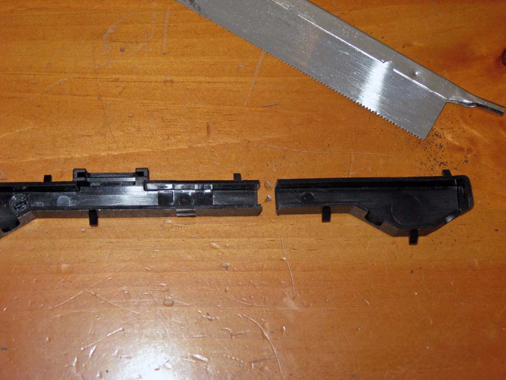
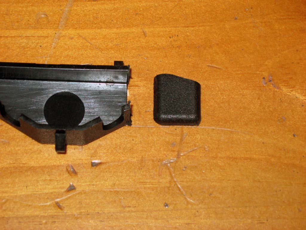
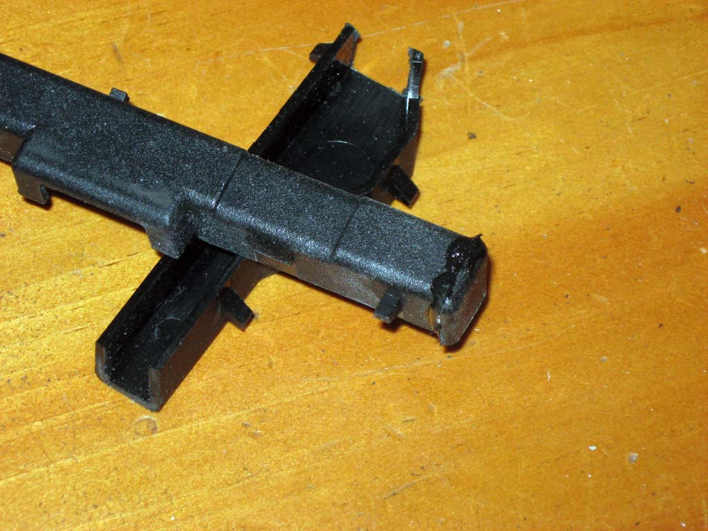
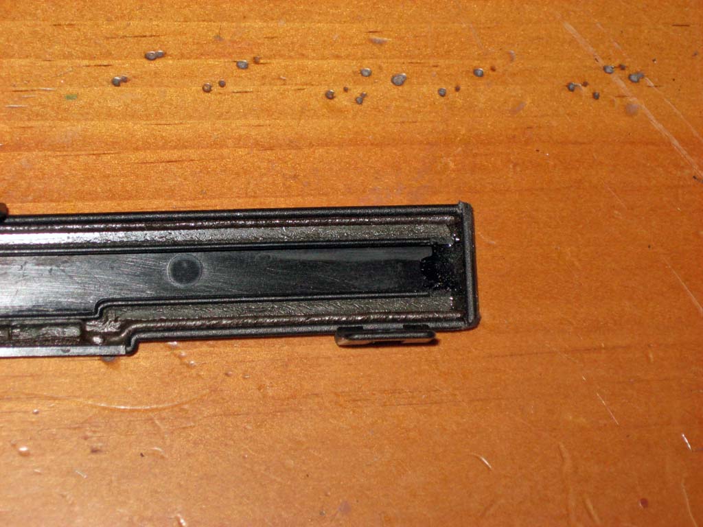
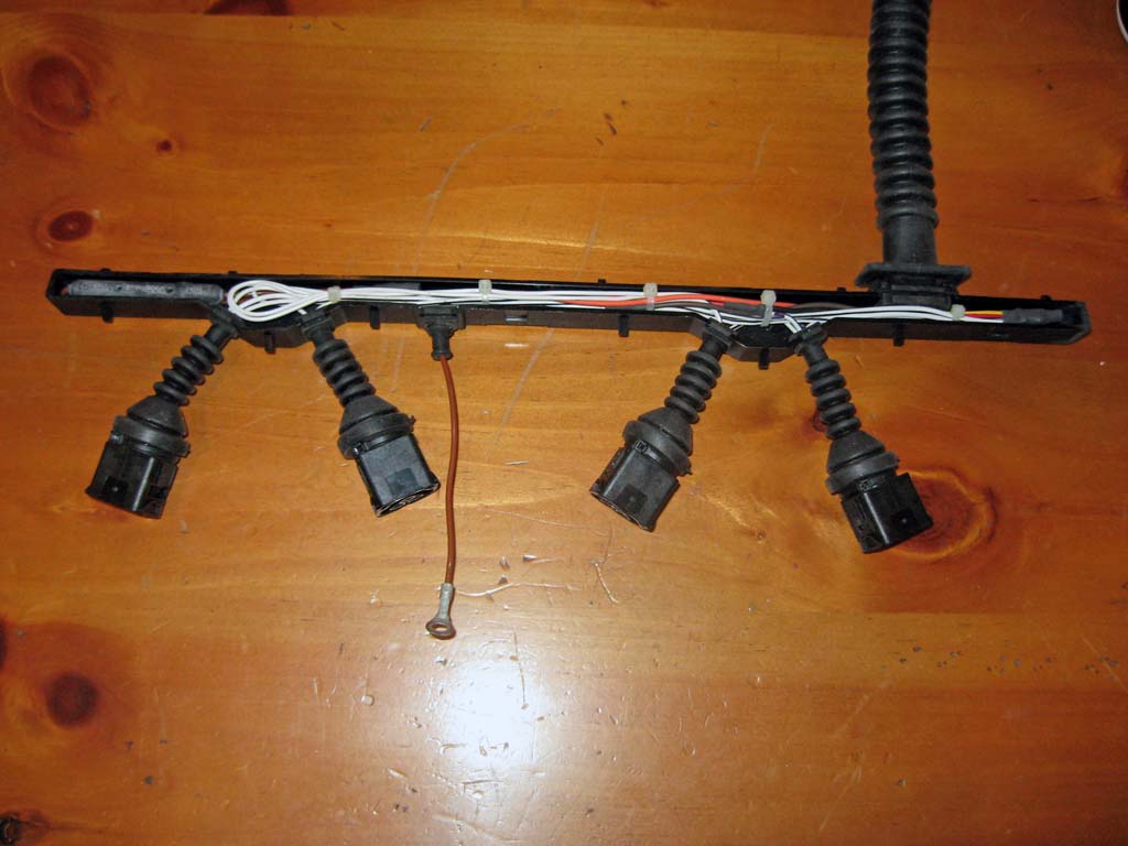
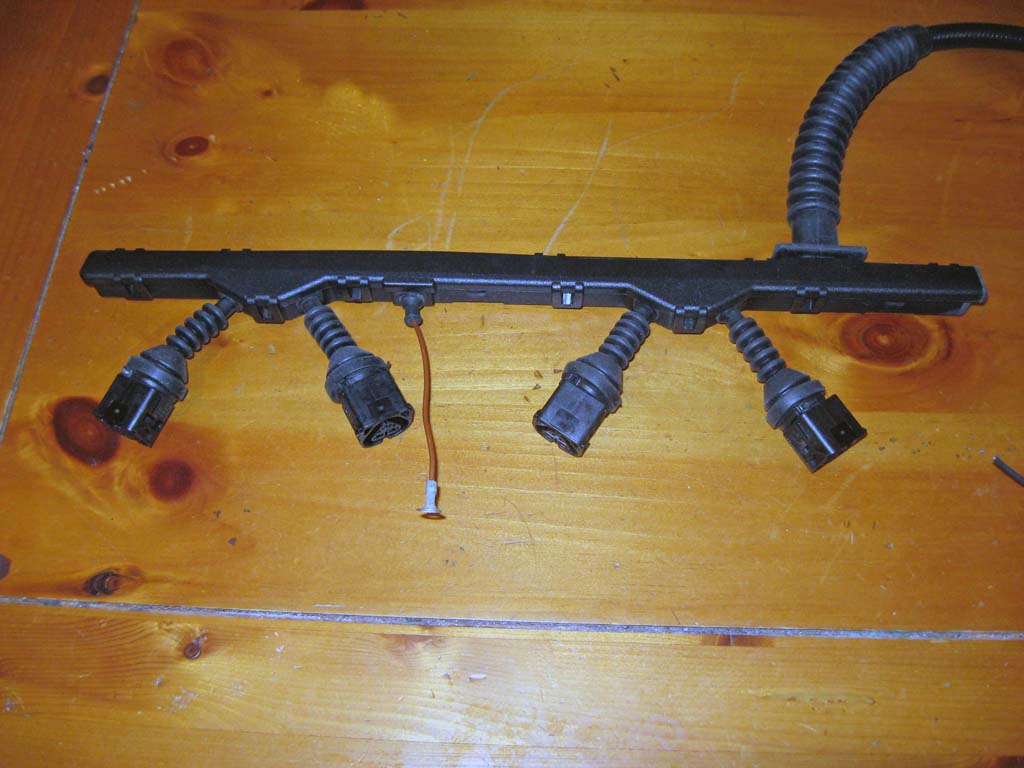
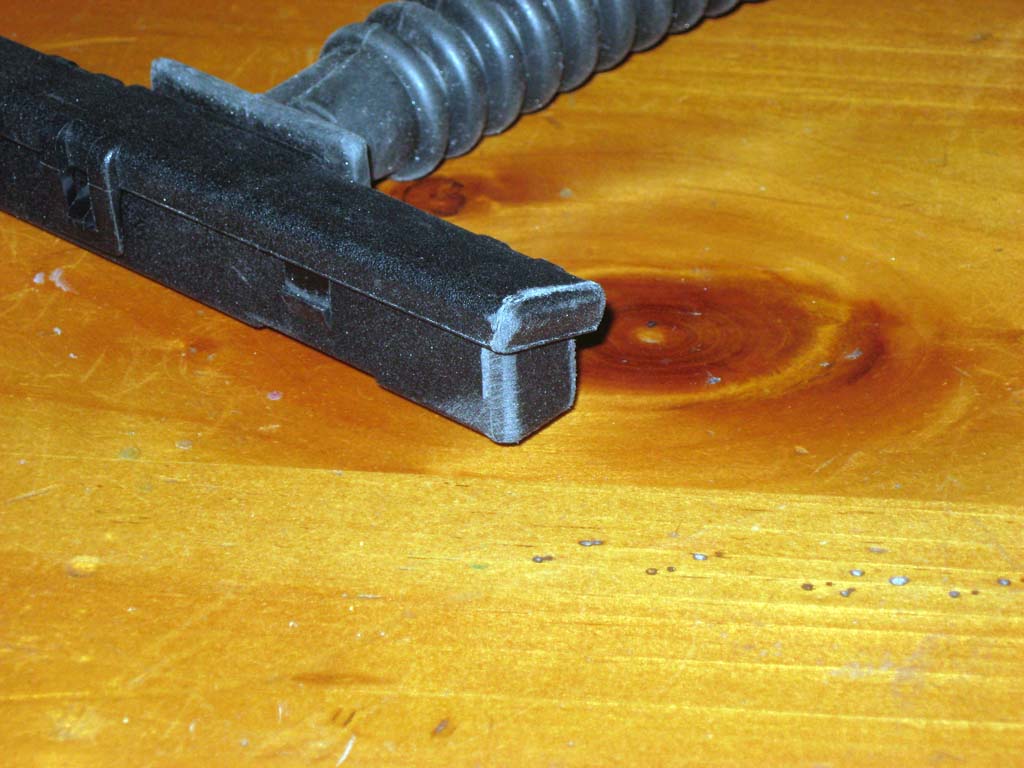
Second Attempt At A Coil Harness Ok, does anyone see the HUGE mistake I made in the design of my first coil harness? Here's a hint, do not use thin walled METAL tubing to run your wires if you cannot fuller de-burr the inside of the tubes. I had sharp edges at each tube junction where the individual coil tubes were soldered to the main tube. I managed to chafe the insulation on several wires, one of the wires had the insulation cut through to the conductor. Fortunately I found the problem while the car was in the garage and not driving. I'm also fortunate that I did not burn up anything when the wire in question intermittently shorted out to the brass tube. The way I fixed this was to create a new harness based on the BMW design. I purchased an E36 ignition harness off of ebay and cut two of the 6 cylinder's coil connections off of it. A little plastic fabrication work to close up the end and it looks almost like a factory piece. Most importantly, it is made of non-conductive plastic this time. The factory rubber grommets and wire covers also work much better than the convoluted tubing and heat shrink tubing used on the first harness. Here is the complete process showing how I modified the E36 piece. I still need to fabricate some simple brackets to tie this piece to my COP bracket.
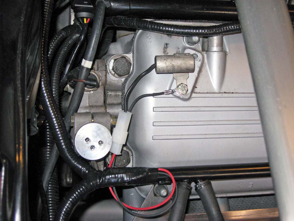
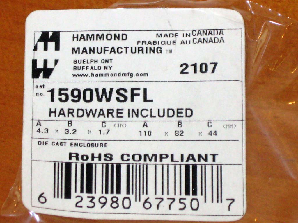
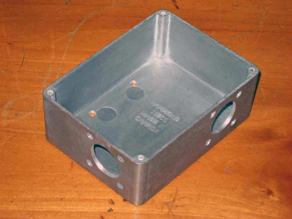
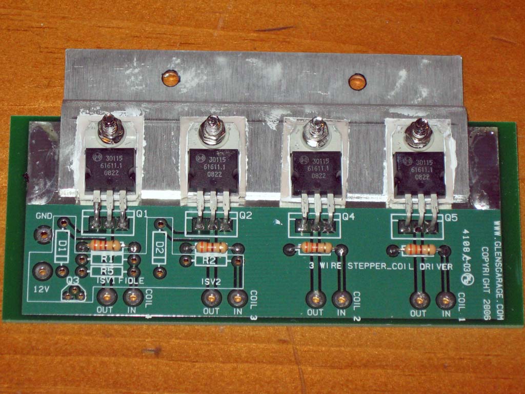
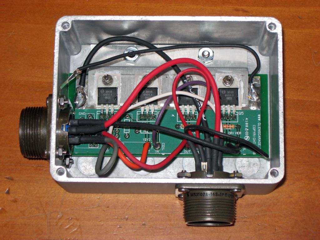
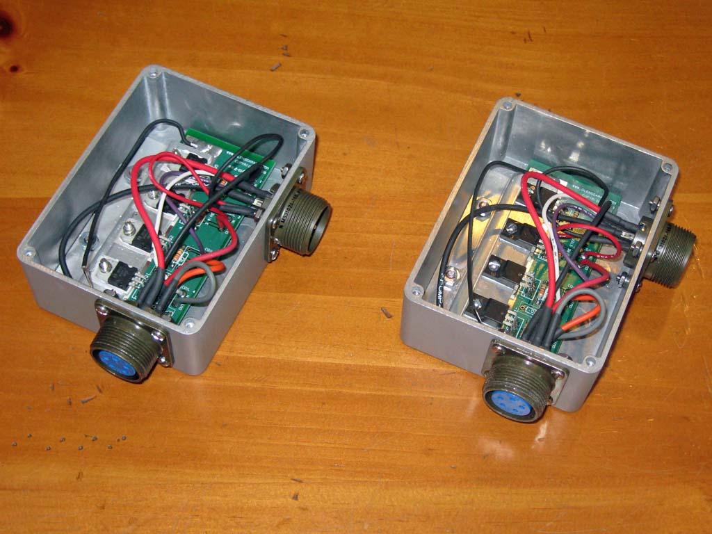
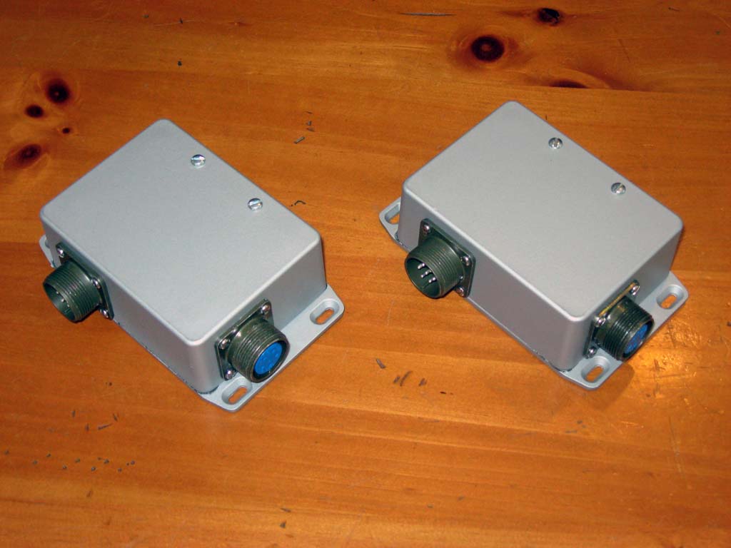
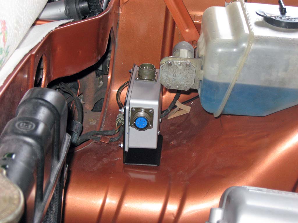
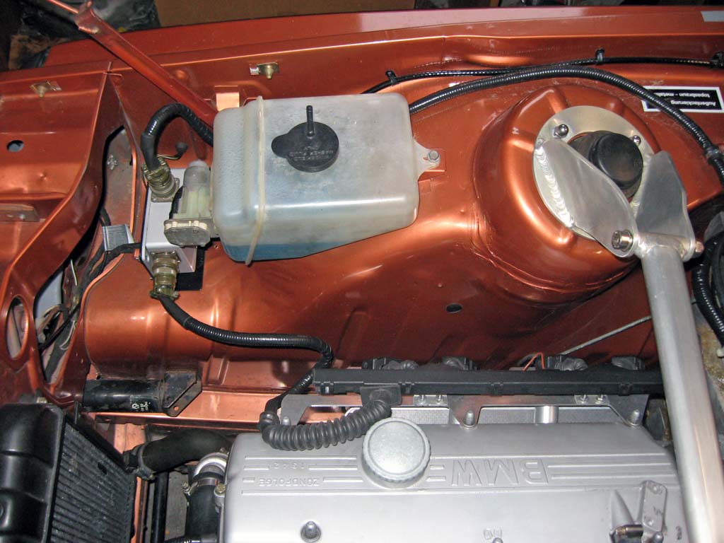
I was having a lot of problems with ignition noise causing problems with my Megasquirt controller. I suspected that these problems were caused by the fact that I had located the high current ignition drivers inside the MS controller case. This choice resulted in a direct connection between my ignition coils and the inside of the MS controller. Not a good choice on my part. I resolved this problem by fabricating a stand-alone ignition driver box to house the ignition drivers that could be located in the engine compartment. I used a combination of a water resistant aluminum box and military-style connectors. I decided to build two copies of this box. If an ignition driver ever died on my, I would be in serious trouble. The spare box was tested on the engine and then added to my spare parts box in the trunk.
What's Next The second prototype coil mounting bracket appears to be the final design. I'm waiting for a sample of a production bracket to verify. I have been driving with various versions of the ignition for the past month. I think the engine is running a little smoother than it was with my wasted spark setup. This might be explained by a plug wire that might have been going out on me. |
||||||||||||||||||||||||||||||||||||||||||||||||||||||||||||||||||||||||||||||||||||||||||||||||||||||||||||||||||||||||||||||||||||||||||||||||||||||||||||||||||||||||||||||||||||||||||||||||||||||||||||
This site was last updated 05/17/10