|
|
Bottom End | |
|
|
Crankshaft | Rods | Pistons | Machine Work | Test Fit | Assembly This page covers the details related to the block, crankshaft, connecting rods, and pistons used on this project. Modifications to the lower timing cover are also shown. Parts Used
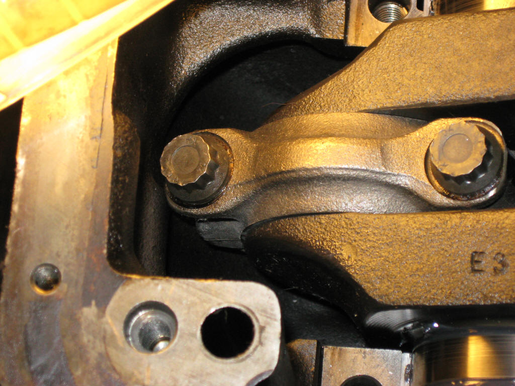
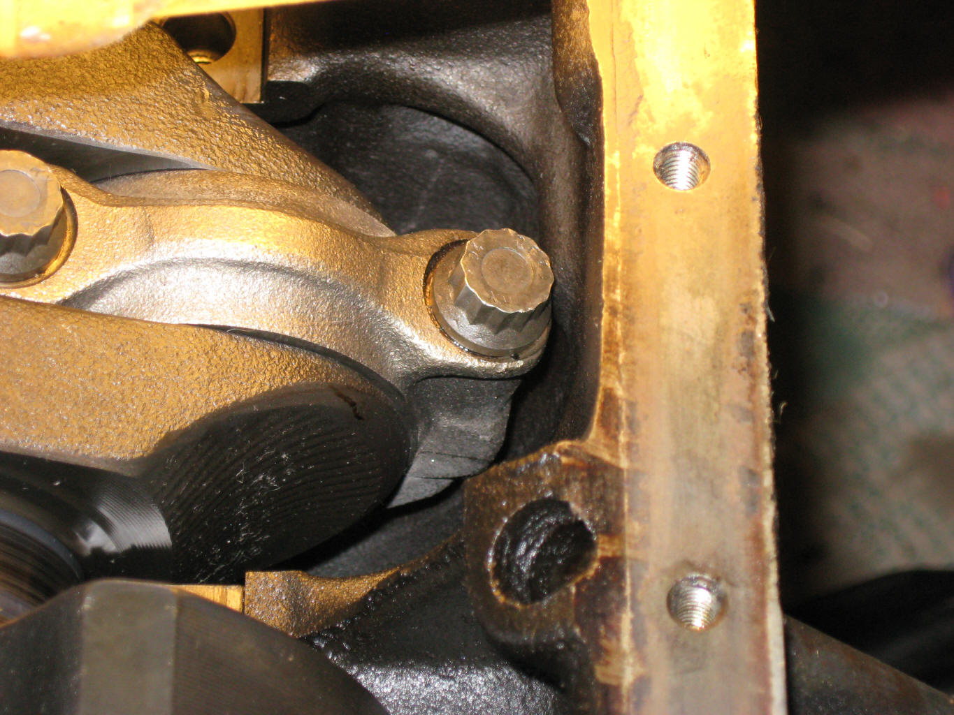
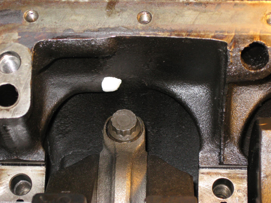
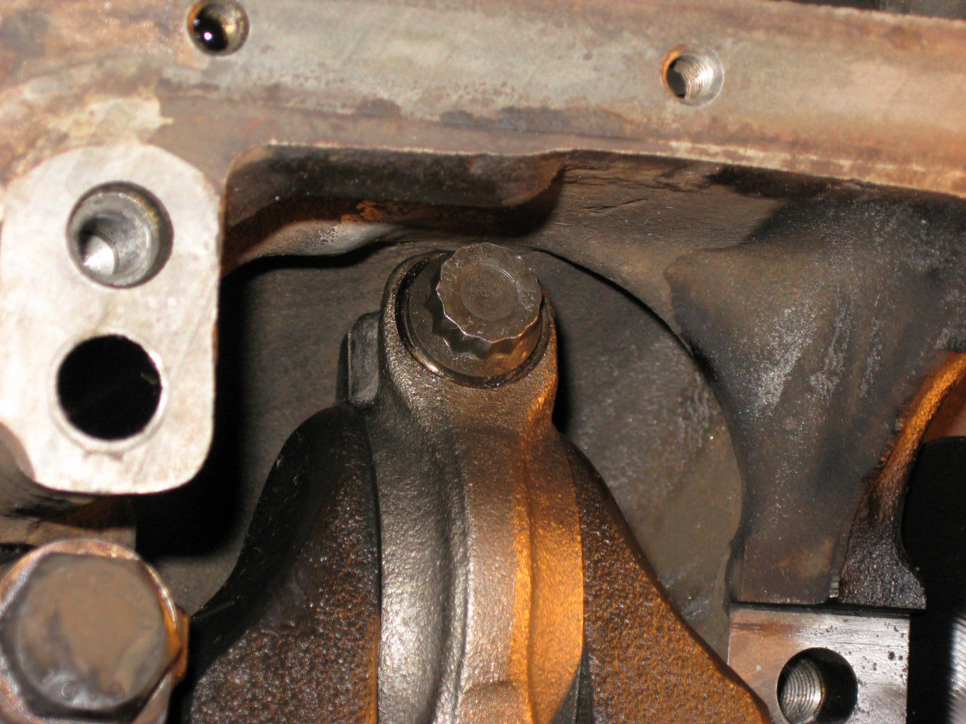
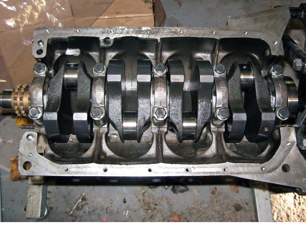
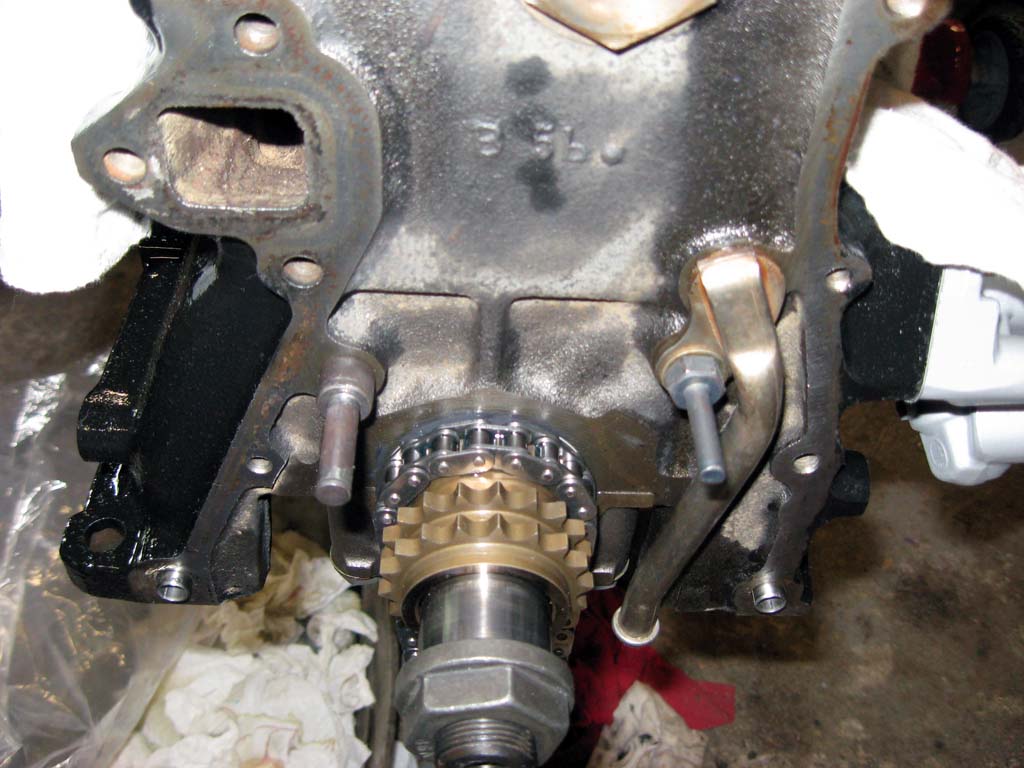
Using a 2.0L block, the S14 crank hits the inside wall in one spot. This is shown here and marked with white paint.
Simply grinding down this one spot removes the interference
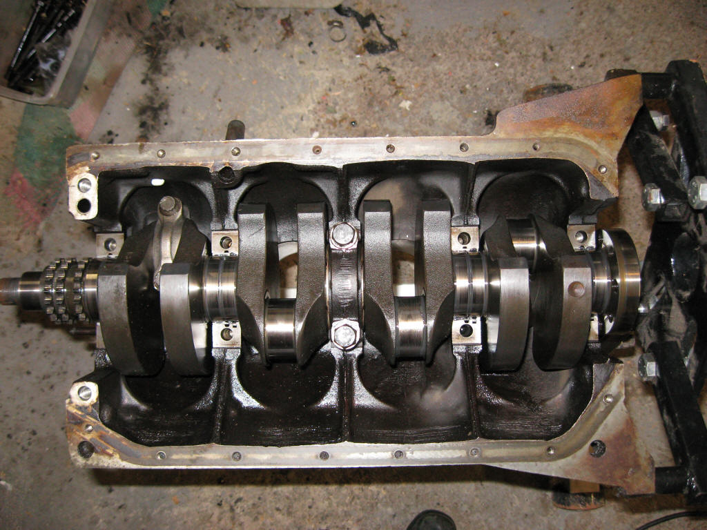
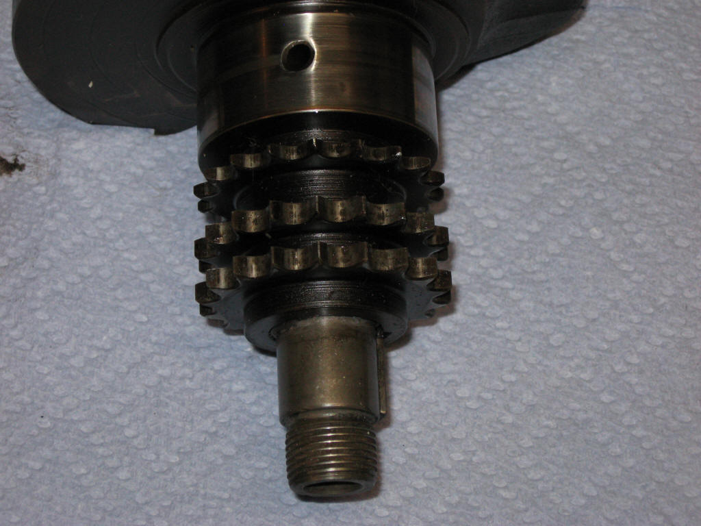
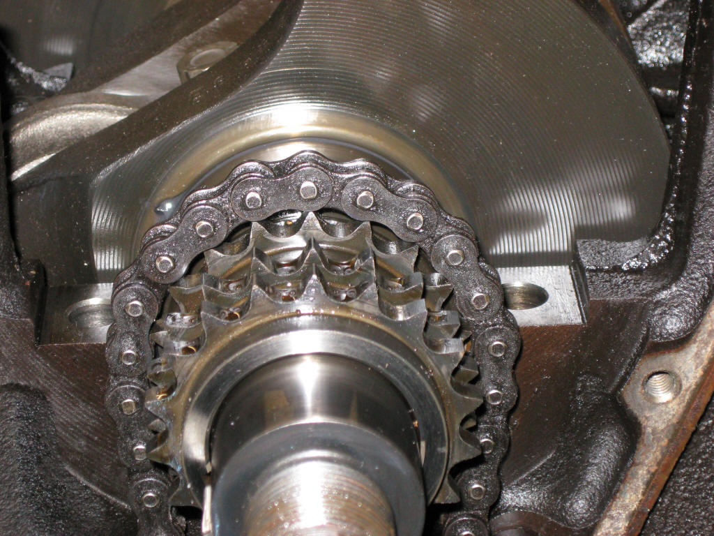
Shown here is the S14 crank (in block) next to the 2.0L M10 crank. The timing chain on the S14 had the same width and pitch as the M10 so that part of the crank gear is the same. The S14 oil pump portion is not compatible with the M10 parts. You need to use the S14 oil pump chain and oil pump gear with the M10 oil pump.
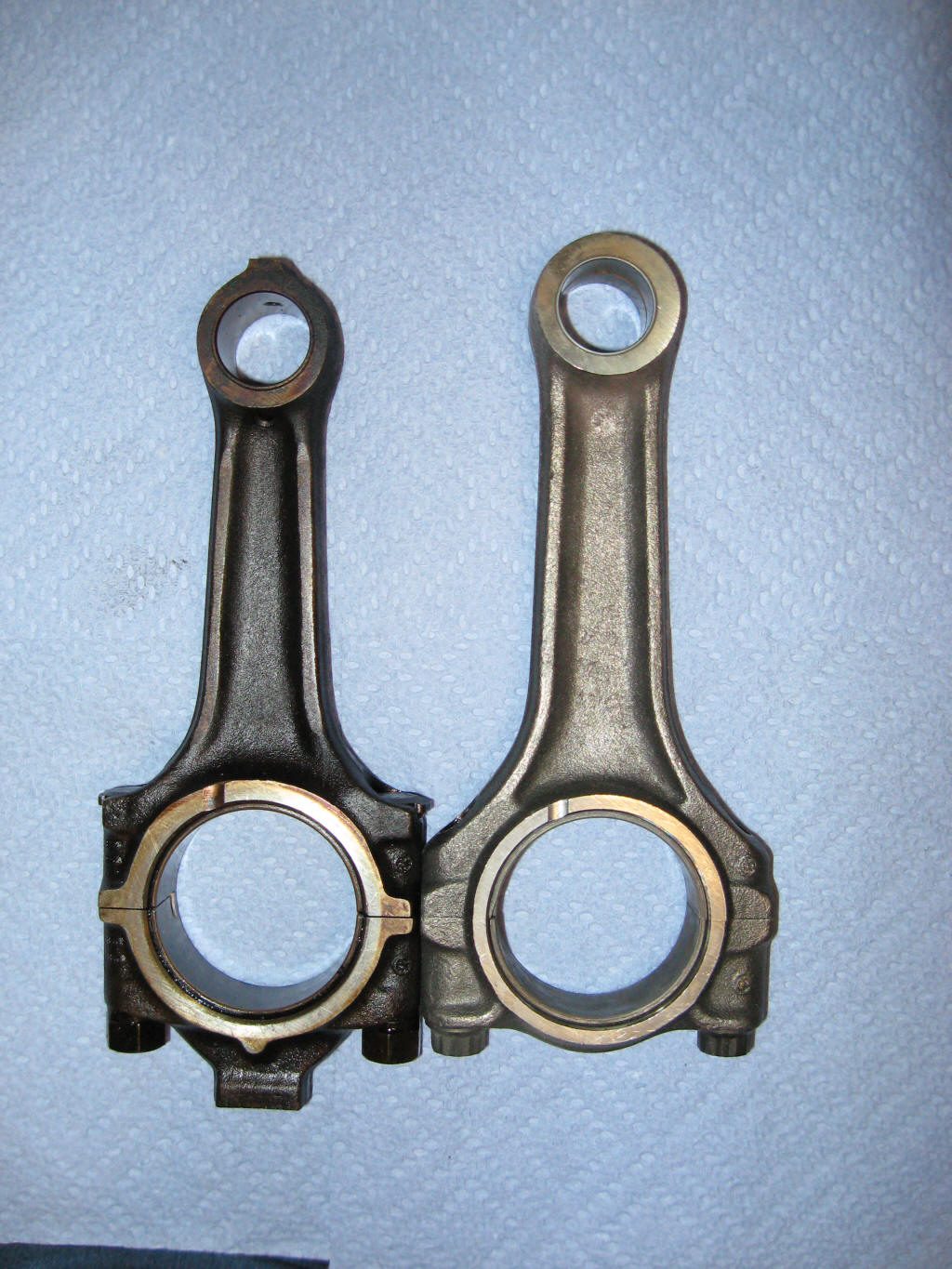
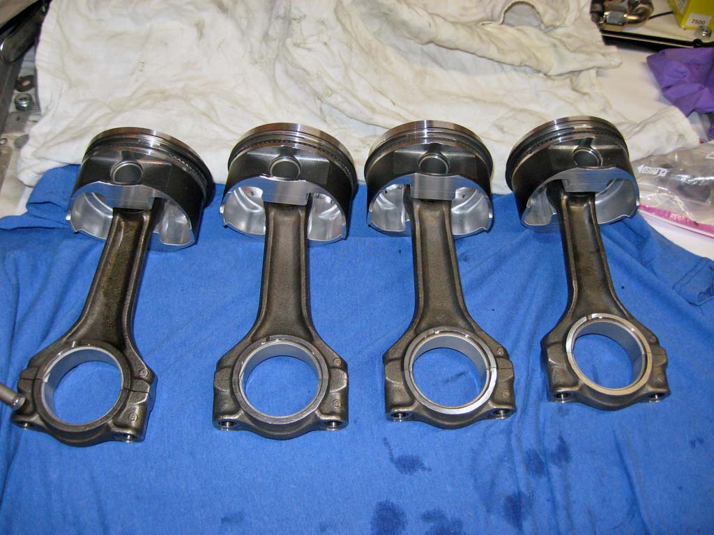
Here is the longer S14 rod next to an M10 rod. The S14 rod is 9mm
longer than the M10 rod.
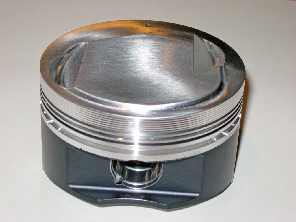
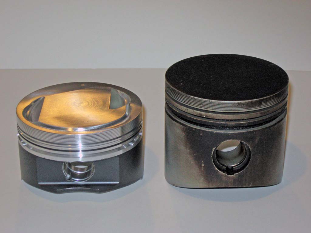
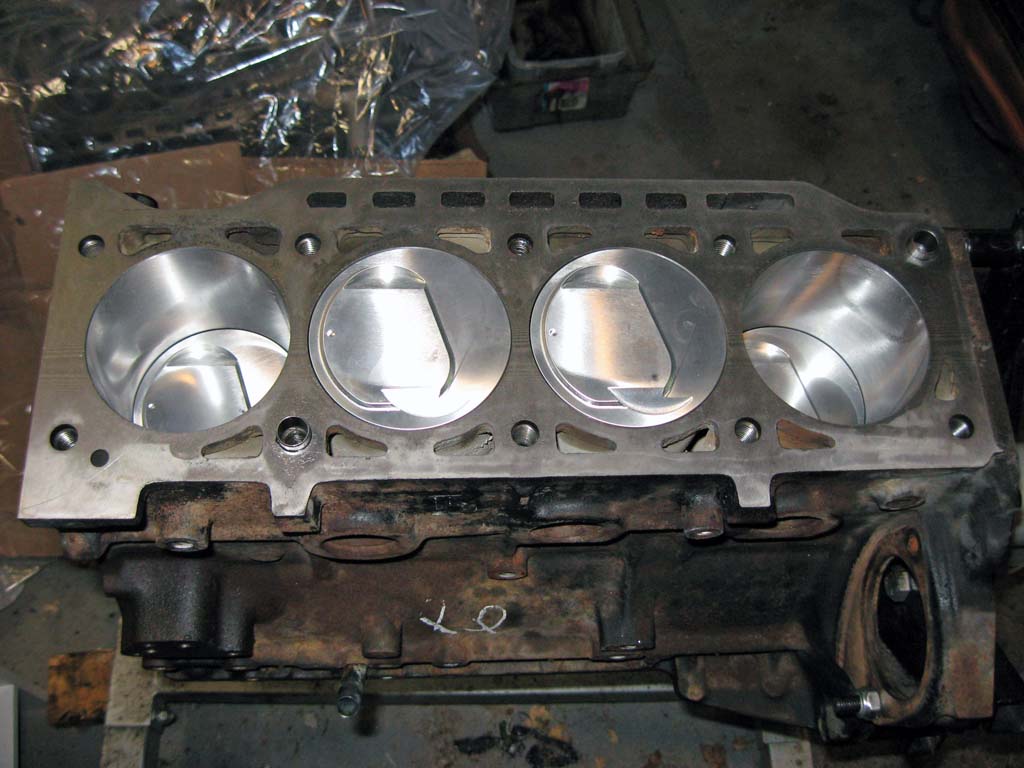
I ordered custom forged pistons from Wiseco. I ordered the pistons sized for a 92mm bore and a 10:1 compression ratio. I also had the side skirts coated to reduce friction. Based on the volume of my combustion chambers (61.6cc), A flat top piston would provide nearly 10:1 compression with no head gasket. When you add in the thickness of the MLS head gasket I plan on using, the piston needed a small (6cc) dome. The dome was shaped to get as close to the edges of the combustion chamber as possible without actually shipping my head to Wiseco. The dome is only 0.08 inches high. These pistons are much lighter than stock and have a compression height of only 1.5 inches to compensate for the longer stroke and rod length. The piston is designed to be .010 inches above the deck at TDC. This will allow the piston to get within about .025 - .030 inches of the squish pad on the cylinder head. This tight clearance will take maximum advantage of the E21 head's small squish pad.
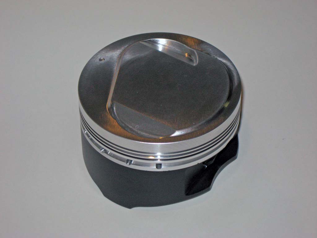
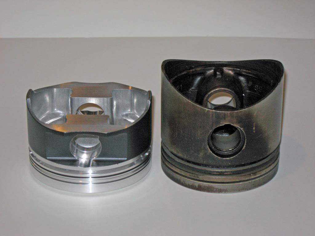
Some pictures of the new piston compared to the stock 2.0L cast piston.
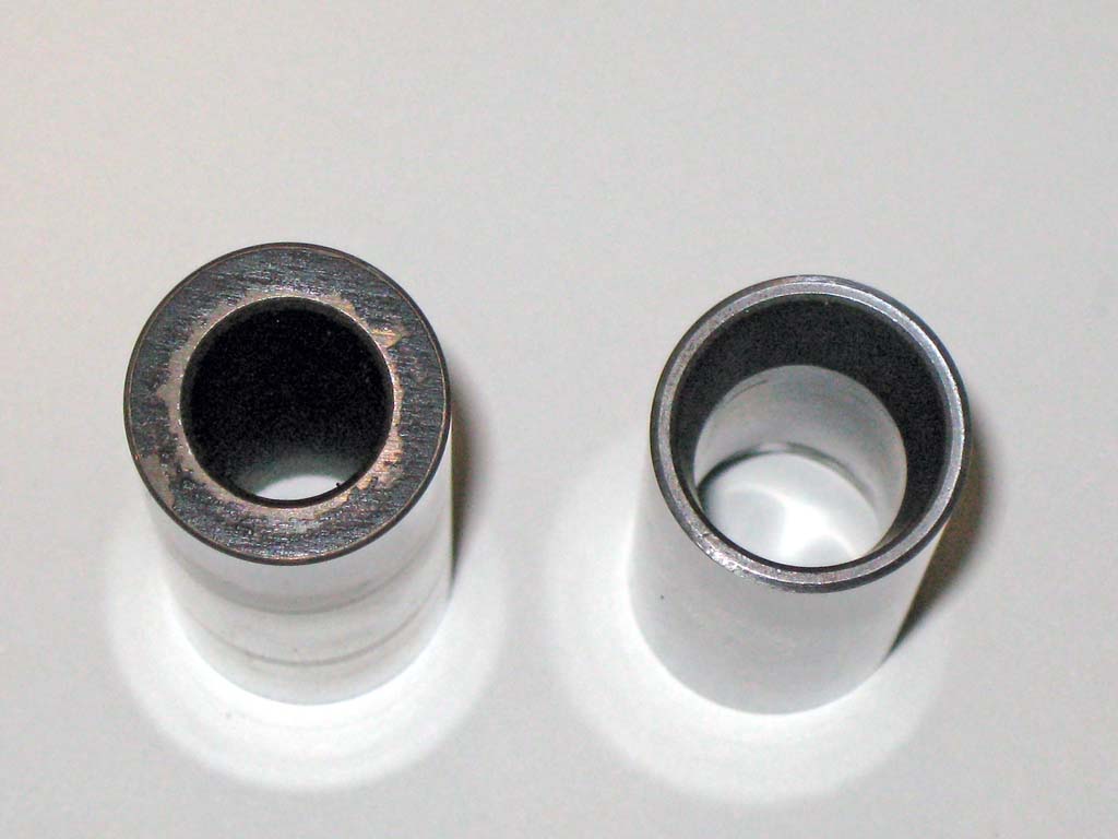
The piston pins Wiseco uses are also lighter than stock. They are shorter than stock and the wall of the pin is tapered on the ends which further reduces weight.
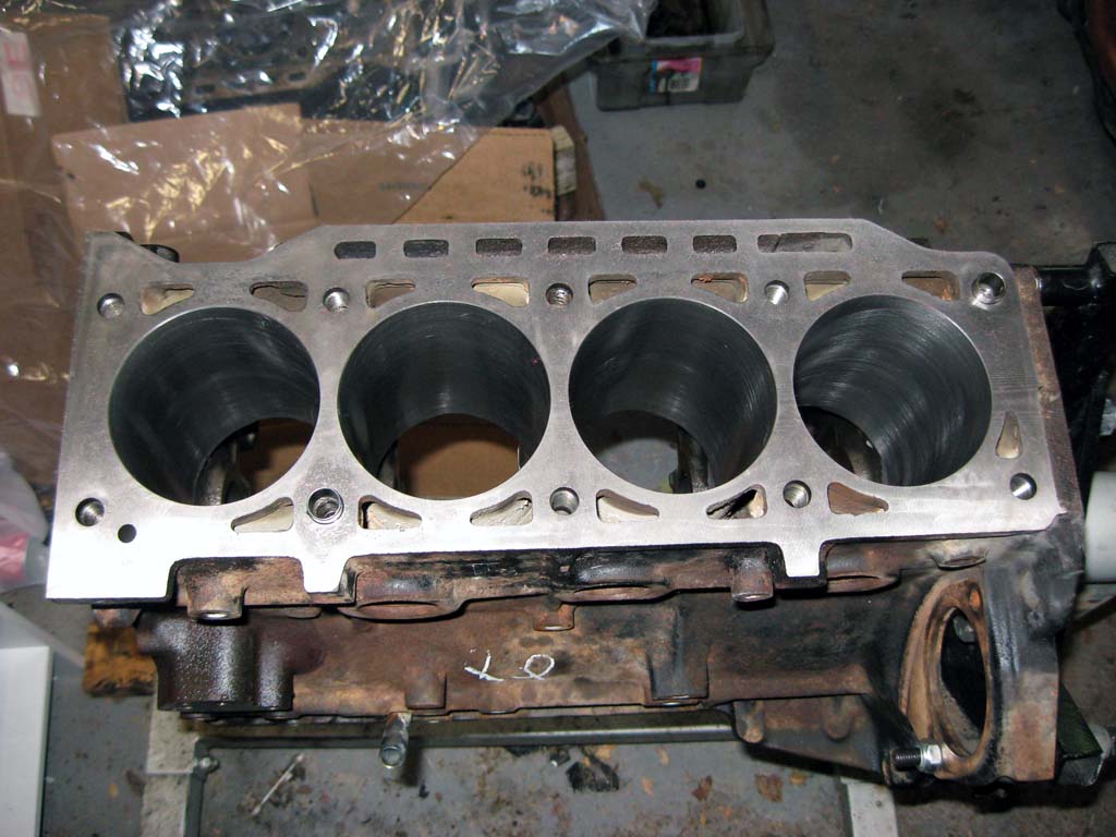
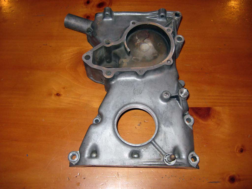
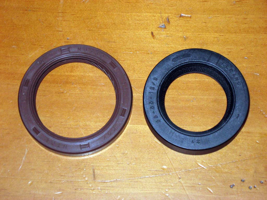
I sent the block, lower timing cover, and rods to my local machine shop to have the required work done. The block was bored out to 92mm to match the pistons. The block was also decked .010 inches to clean up the surface. The lower timing cover was modified to accept the larger S14 front oil seal. Fortunately there was no work required on the rods.
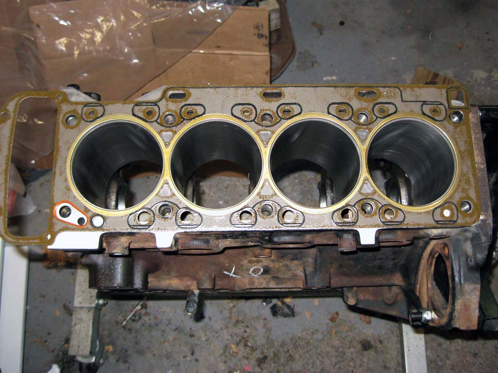
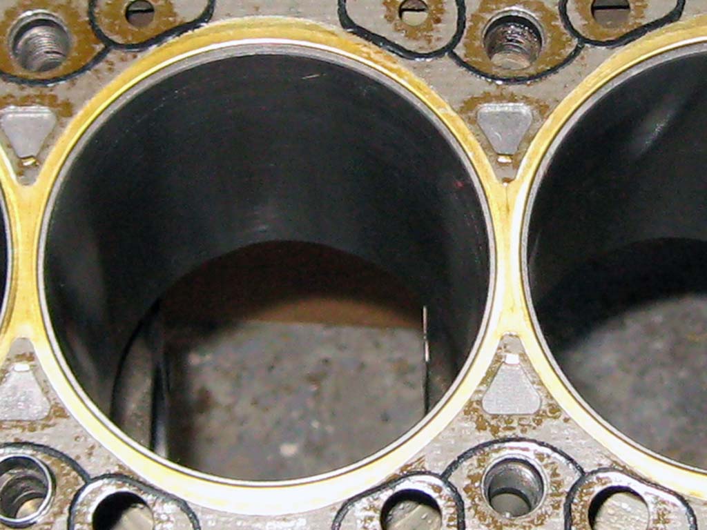
The deck height of the pistons at TDC was checked, the pistons end up between .020 and .025 inches above the deck at TDC. My calipers are not accurate enough to get an exact measurement. The compressed thickness of the S14 head gasket is about .070 inches. This will give be a clearance between the piston and the squish pad on the head of between .045 and .050 inches. The piston to head clearance was checked using
an old used S14 head gasket and some modeling clay. The valves
don't even come close to the head, and the piston to head clearance is
about .050 inches as expected.
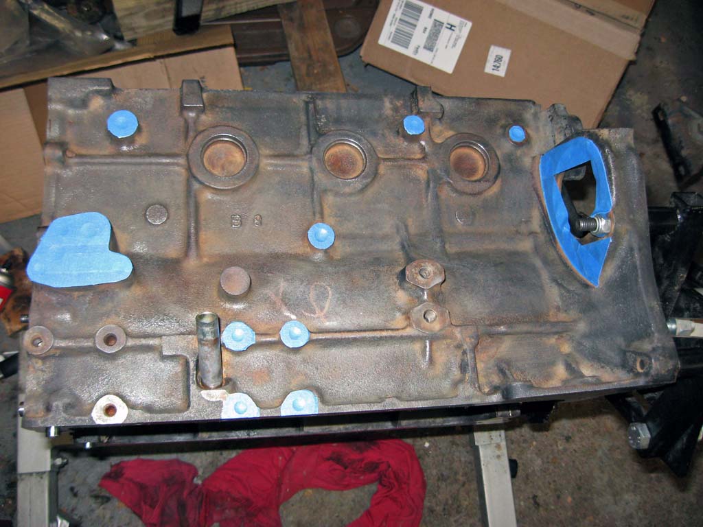
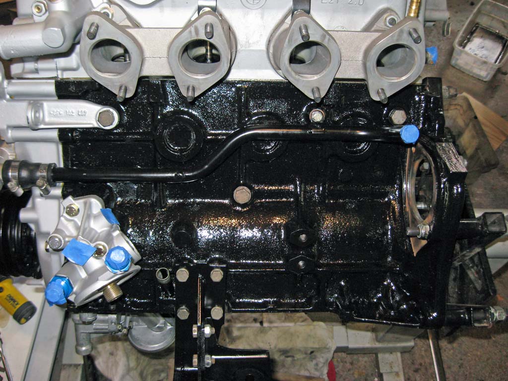
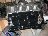
After checking the piston clearance, the block was torn back down and I spend a few hours with brake cleaner, a wire brush, and Q-tips cleaning the block inside and out. Don't assume just because a block has been hot tanked that it is clean! When this amount of machine work is done to a block, the residue ends up everywhere. A good amount was still stuck to the inside of the main oil galley.
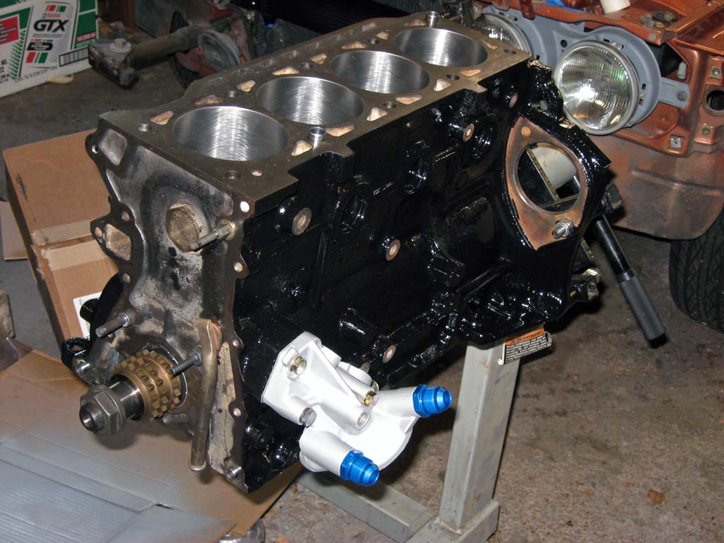
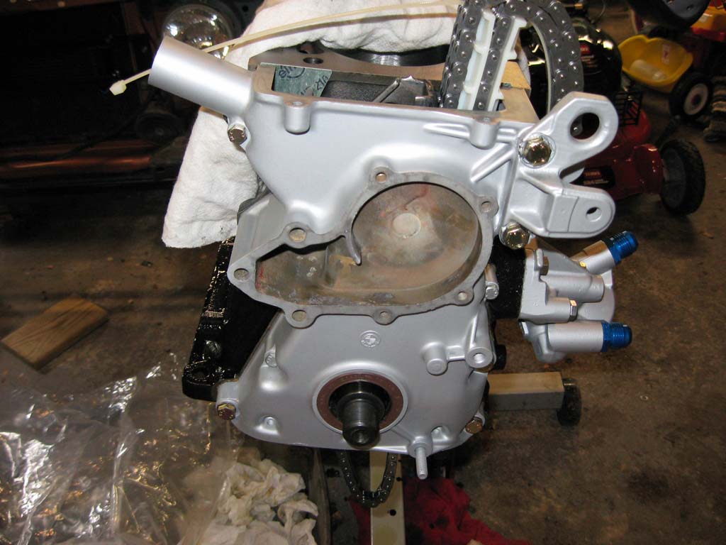
I am painting all the aluminum engine parts with another Eastwood product they call Aluma Blast. I saw this used on someone else's car and thought they had powder-coated the parts. This paint is a nice low-gloss aluminum color that will make keeping the engine clean a lot easier.
Just before installing the crank, I gapped the piston rings.
The rings were gapped to Wiseco's specifications, .016 for the top ring
and .020 for the 2nd ring. The rings were installed on the pistons
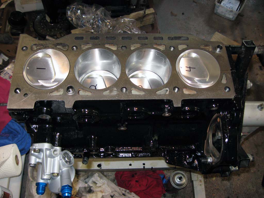
and the pistons and rods assembled. Before installing the pistons,
you need to clean the cylinder bores. I prefer to use paper towels
and WD-40. I wet down a paper towel with WD-40 and wipe out the
bores. I keep doing this until the paper towels stay clean.
It took about 6 to 8 wipe-downs to get the bores clean. This is an
important step in helping the rings seat correctly. You need to
get all the dirt out of the grooves created when the cylinder is honed.
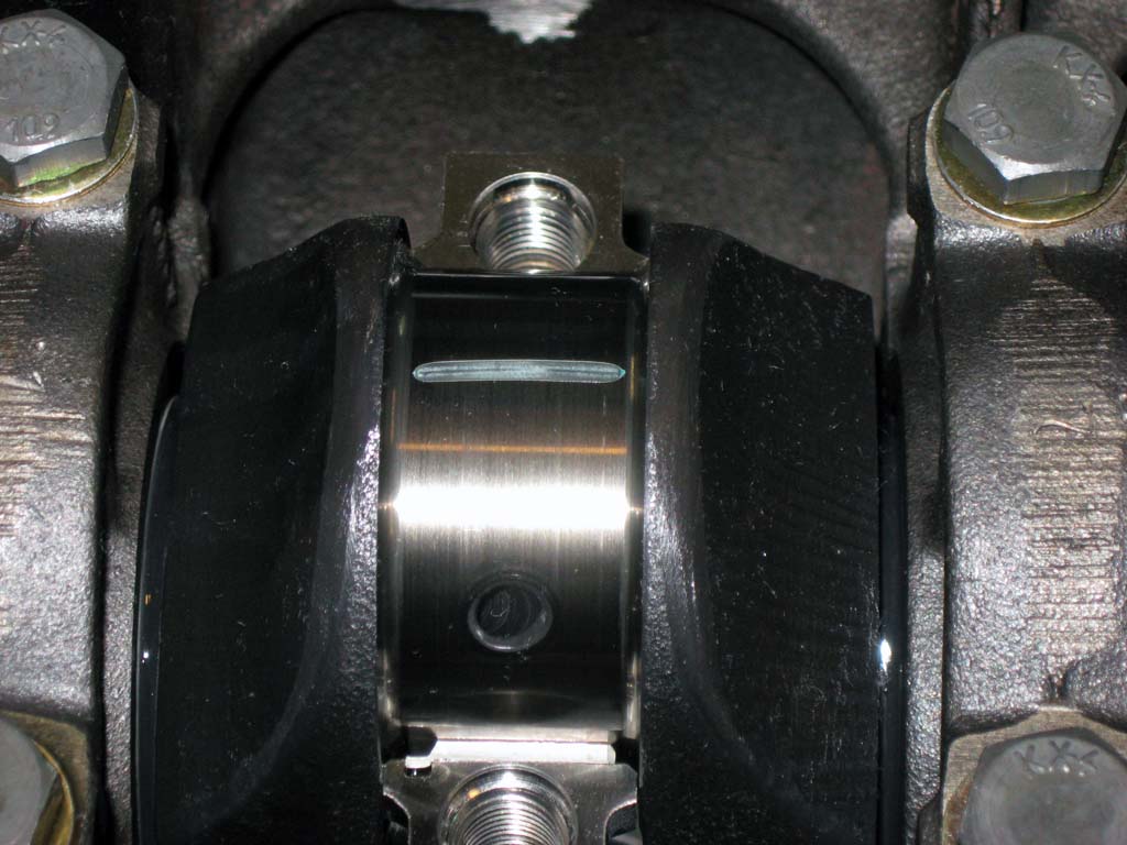
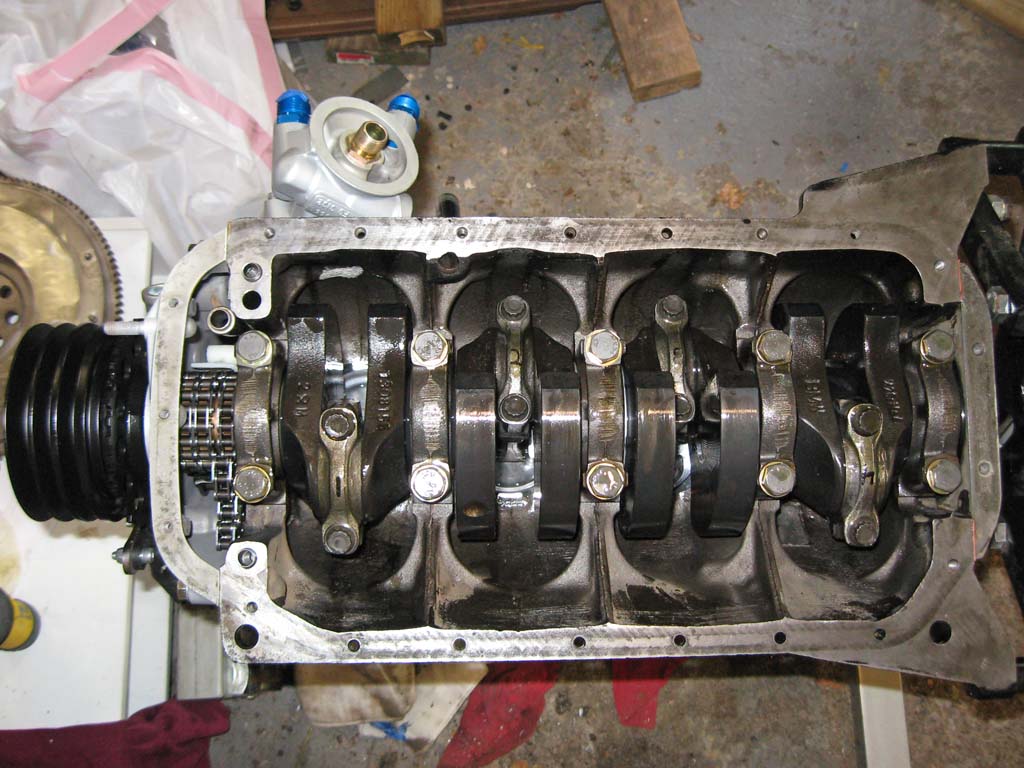
Rod bearing clearances were checked with plasti-gauge.
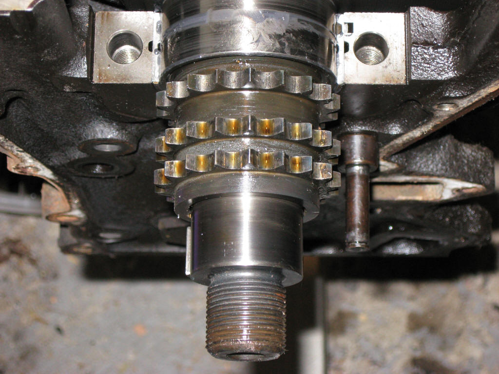
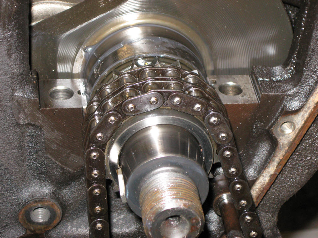
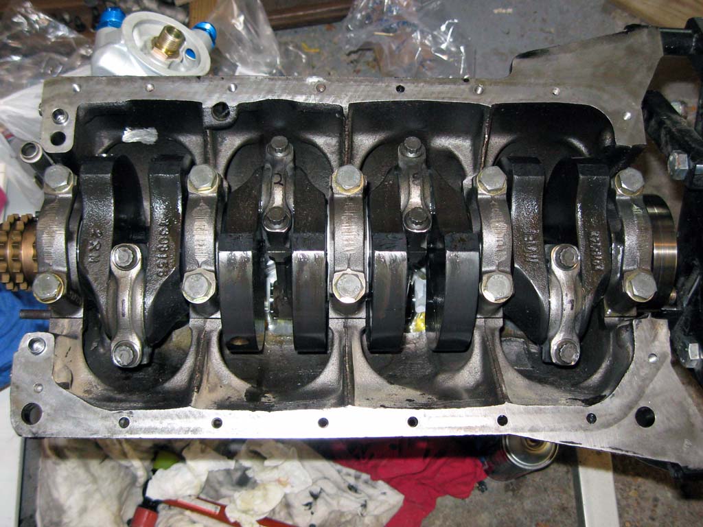
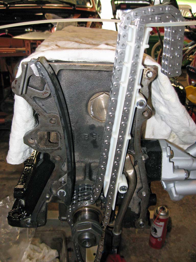
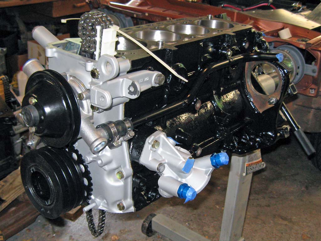
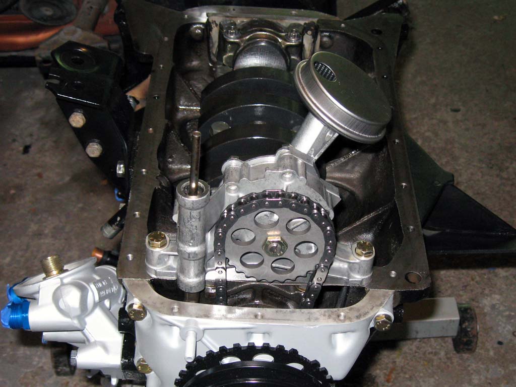
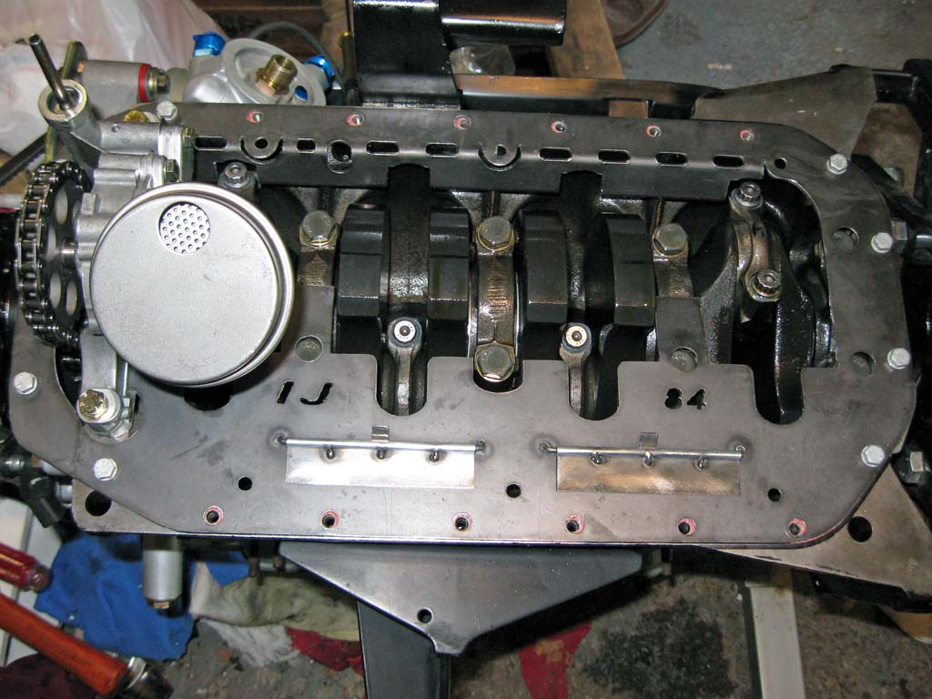
I'm waiting for the ARP rod bolts to arrive, so I cannot install the oil pump yet. The rods are currently installed with the original OEM rod bolts. I decided to install the chains and the front timing cover. I can build up the entire motor and install the oil pump last.
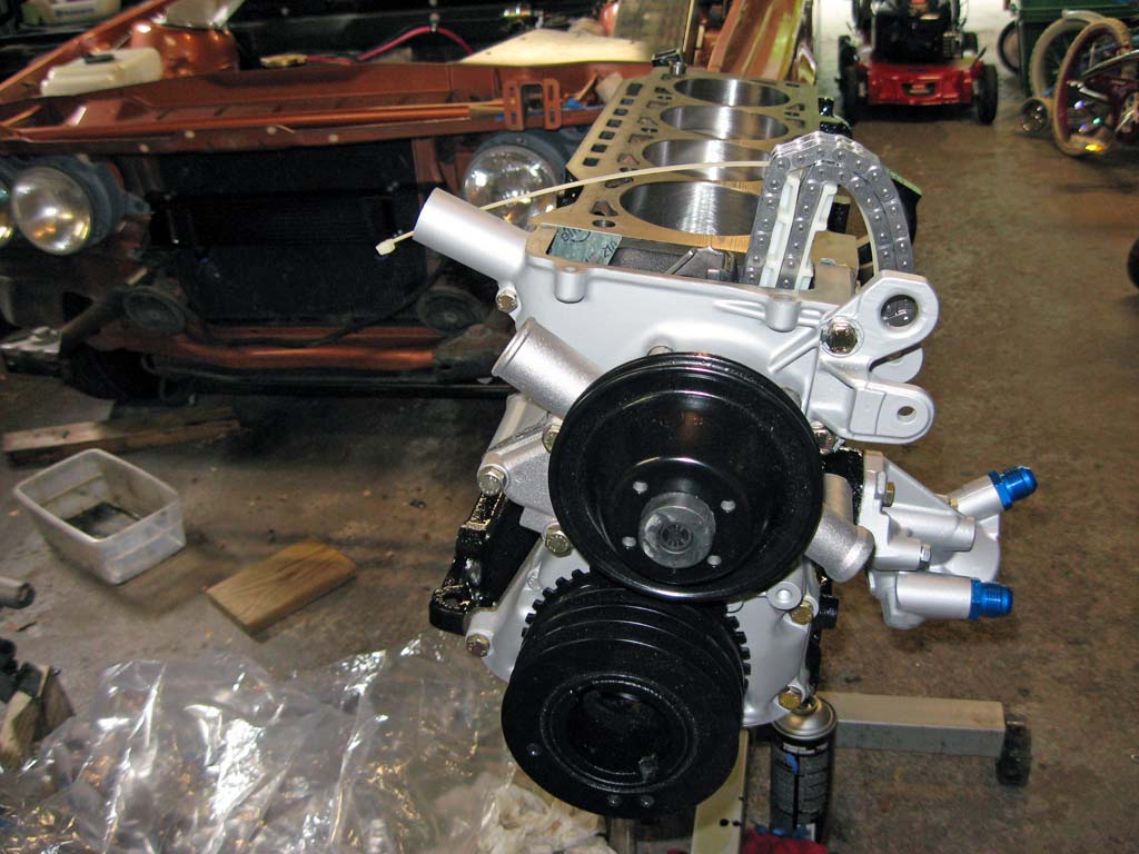
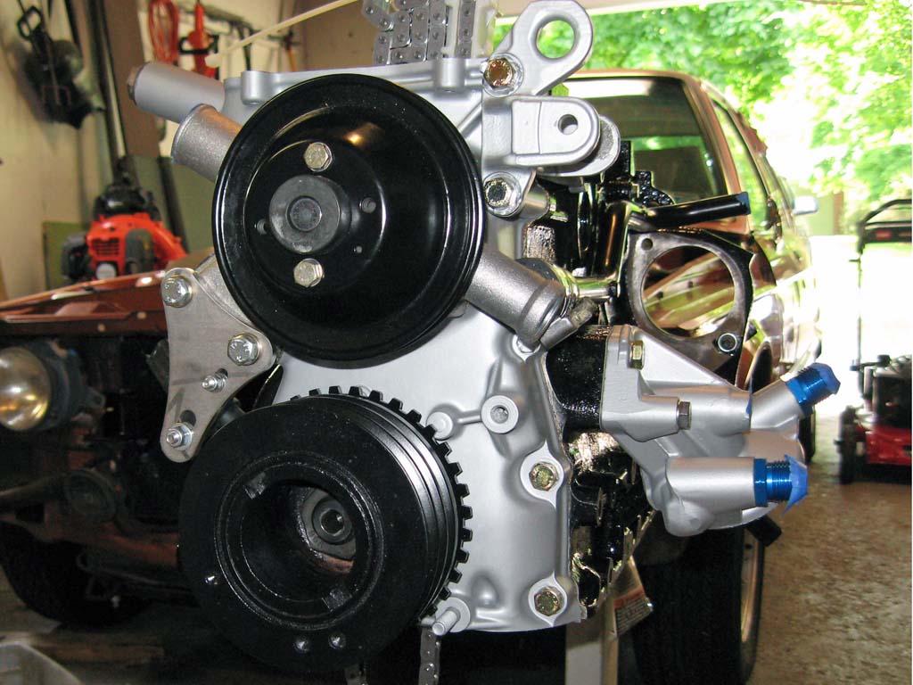
The next pieces installed were the 2002 water pump and pulley along with the harmonic balancer. The VR sensor pickup for the crankshaft toothed wheel was installed as well as the coolant bypass pipe.
I received my ARP S14 rod bolts and installed them per the ARP installation instructions. I do not own the tools necessary to accurately measure bolt stretch so I followed the alternate instructions provided that only require a regular torque wrench.
|
||||||||||||||||||||||||||||||||||||||||||||||||||||||||||||||||||||||||||||||||||||||||||||||||||||||||||||||||||||||||||||||||||||||||||||||||||||||||||||||||||||||||||||||||||||||||||||||||||||||||||||||||||||||||||||||||||||||||||||||||||||||||||||||||
This site was last updated 12/29/09